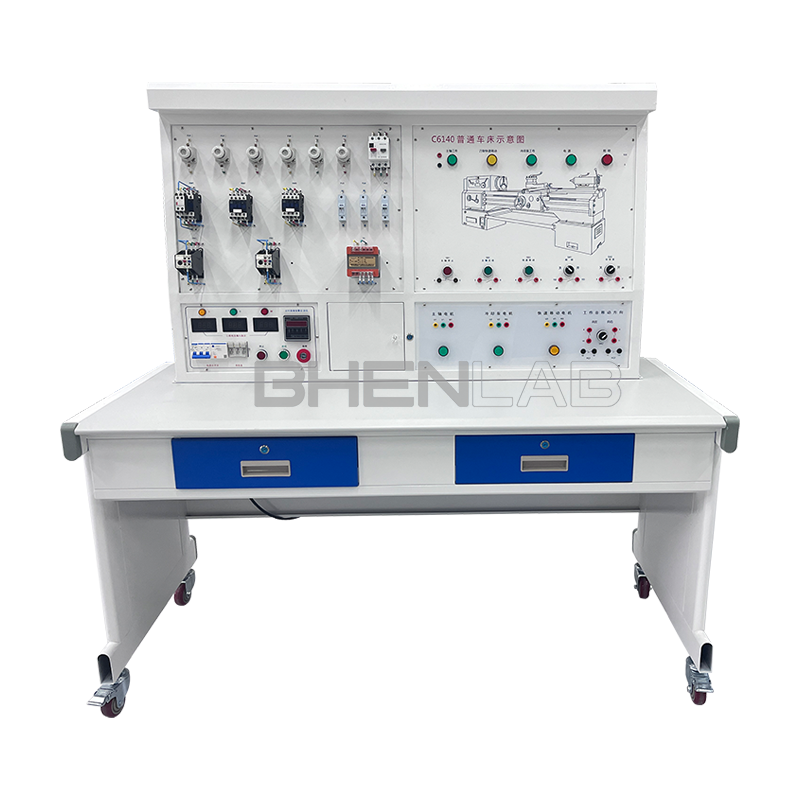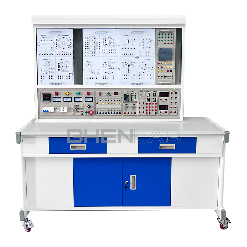


This machine tool electrical skill training and assessment experimental device is developed for the teaching and assessment of electrical control content in colleges and universities, vocational schools’ electrical, automation and related majors, social electrician training, and county-level maintenance electrician identification institutes (stations). It can be used for classroom demonstrations, principle operations and experimental internships of machine tool electrical control. The device artificially and secretly sets dozens of circuit faults. With the help of principle analysis, students can receive comprehensive and real machine tool electrical fault elimination training. It is an ideal equipment for skill training and assessment, with remarkable teaching effects.
I. Basic Configuration of the Experimental Device
- AC power supply (with leakage protection measures): Provide three-phase AC power supply (380V)
- Personal safety protection system: A voltage-type leakage protection device is installed on the screen. If there is a leakage in the control screen or strong electricity output, the power supply will be cut off to ensure the safety of the experiment process.
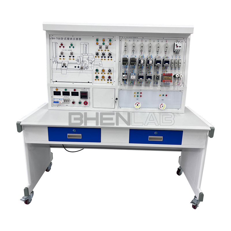
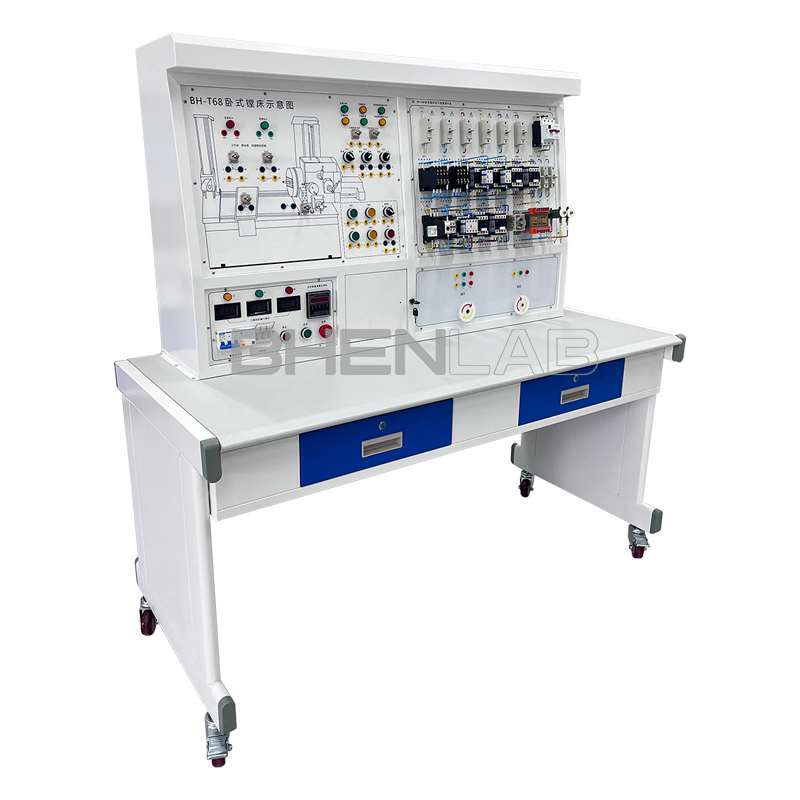
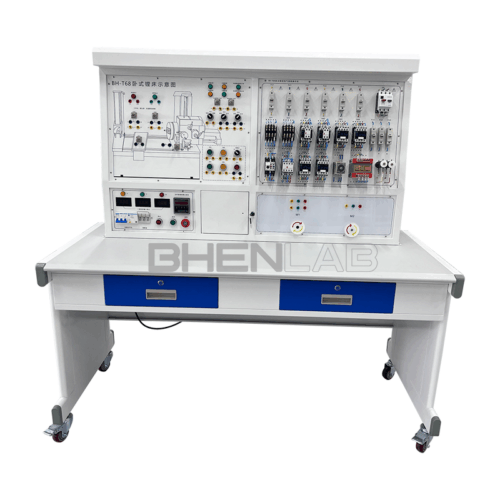
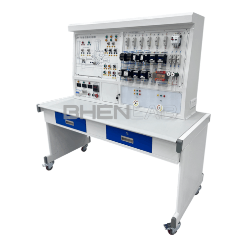
- Three-dimensional color map of the machine tool: The panel is printed with a color three-dimensional outline drawing of each machine tool, so that the outline of various machine tools can be seen intuitively, and the machine tool form is realistic.
- Three-phase asynchronous motor: The experimental platform is equipped with 2 three-phase squirrel-cage asynchronous motors, which are used as double-speed motors, fast-moving motors, etc. respectively.
- Fault switch box: Equipped with 25 fault switches.
- Experimental desk: The experimental desk is of iron double-layer sub-gloss dense-grain spray plastic structure, with a density board desktop. It has a solid structure, a cuboid-like shape, and an elegant appearance; it is equipped with two large drawers for placing tools and materials, etc. The desktop is used to install the power control screen and provide a spacious work surface.
II. Experimental Projects and Main Contents:
- Students are familiar with the structure and principle of common low-voltage electrical appliances.
- In the electrical schematic mode, with the help of principle analysis, students can find the fault point on a certain line through measurement.
- Improve students’ hands-on ability and skill operation level.
- Complete the elimination of common faults of the machine tool through machine tool fault elimination.
- Fault points can be set as a skill assessment platform for maintenance electricians.
III. Technical Performance:
1.Input power supply: Three-phase four-wire 380V AC power supply.
2.Structure: The experimental platform is of iron sheet metal spray plastic structure, which is firm and durable.
3.Working environment: Temperature -100 – +400°C.
- Total power consumption: <2KW
List of Electrical Configurations of the Experimental Platform:
| Code | Code | Component Name | Quantity | Use |
| M1 | M1 | Double-speed motor | 1 | Drive the spindle |
| M2 | M2 | Motor | 1 | Drive feed |
| QS1 | QS1 | Switch | 1 | Main switch |
| QS2 | QS2 | Switch | 1 | Cooling pump switch |
| SA1 | SA1 | Switch | 1 | Tool change switch |
| SA2 | SA2 | Switch | 1 | Circular worktable switch |
| SA3 | SA3 | Switch | 1 | M1 phase change switch |
| FU1 | FU1 | Fuse | 1 | Power insurance |
| FU2 | FU2 | Fuse | 1 | |
| FU3 | FU3 | Fuse | 1 | |
| FR | FR | Thermal relay | 1 | M1 overload protection |
| T | T | Transformer | 1 | Rectification, circuit, lighting power supply |
| KM1 | KM1 | Contactor | 1 | Spindle forward rotation |
| KM2 | KM2 | Contactor | 1 | Spindle reverse rotation |
| KM3 | KM3 | Contactor | 1 | Spindle braking |
| KM4 | KM4 | Contactor | 1 | Spindle low speed |
| KM5 | KM5 | Contactor | 1 | Spindle high speed |
| KM6 | KM6 | Contactor | 1 | M2 forward rotation fast |
| KM7 | KM7 | Contactor | 1 | M2 reverse rotation fast |
| KA1 | KA1 | Intermediate relay | 1 | Turn on spindle forward rotation |
| KA2 | KA2 | Intermediate relay | 1 | Turn on spindle reverse rotation |
| SB1 | SB1 | Button | 1 | Spindle stop |
| SB2 | SB2 | Button | 1 | Spindle forward start |
| SB3 | SB3 | Button | 1 | Spindle reverse start |
| SB4 | SB4 | Button | 1 | Spindle forward inching |
| SB5 | SB5 | Button | 1 | Spindle reverse inching |
| SQ | SQ | Position switch | 1 | Turn on high speed |
| SQ1 | SQ1 | Position switch | 1 | Interlock between spindle feeding and worktable movement |
| SQ2 | SQ2 | Position switch | 1 | Interlock between spindle feeding and worktable movement |
| SQ3 | SQ3 | Position switch | 1 | Feed speed change |
| SQ4 | SQ4 | Position switch | 1 | Spindle speed change |
| SQ5 | SQ5 | Position switch | 1 | Feed speed change |
| SQ6 | SQ6 | Position switch | 1 |
Fault Phenomena:
| G1 | The machine tool cannot start | Both the spindle motor and the fast-moving motor cannot start. |
| G2 | Spindle forward rotation cannot start | Pressing the forward start button has no response. |
| G3 | Spindle forward rotation cannot start | Pressing the forward start button has no response. |
| G4 | The machine tool cannot start | Both the spindle motor and the fast-moving motor cannot start. |
| G5 | Spindle reverse rotation cannot start | Pressing the reverse start button has no response. |
| G6 | Spindle reverse rotation cannot start | Pressing the reverse start button has no response. |
| G7 | Spindle forward rotation cannot start | When forward rotation is started, KA1 pulls in, and there is no other action; When reverse rotation is started, KA2 pulls in, and there is no other action |
| G8 | Reverse start can only be inching | Forward start is normal, and pressing SB3 for reverse start can only be inching. |
| G9 | Spindle cannot start | When forward rotation is started, KA1 pulls in, and there is no other action; When reverse rotation is started, KA2 pulls in, and there is no other action |
| G10 | Spindle has no high speed | When high speed is selected, KT and KM5 have no action. |
| G11 | Spindle and fast-moving motor cannot start | When forward rotation is started, KA1 and KM3 pull in, and there is no other action; When reverse rotation is started, KA2 and KM3 pull in, and there is no other action; Pressing SQ8 and SQ9 has no response. |
| G12 | No braking when stopping | |
| G13 | No braking when stopping | |
| G14 | Spindle motor cannot rotate forward | Reverse rotation is normal. |
| G15 | Spindle can only be controlled by electric | Forward and reverse rotation cannot be started, only electric control is available. |
| G16 | Spindle motor cannot reverse | Forward rotation is normal. |
| G17 | Spindle and fast motor cannot start | KM4 and KM5 cannot pull in; No response when pressing SQ8 and SQ9. |
| G18 | Spindle forward rotation can only be inching | KM4 (low speed) and KM5 (high speed) cannot be maintained. |
| G19 | Spindle has no high speed | KT acts, KM4 will not release, and KM5 cannot pull in. |
| G20 | Spindle reverse rotation can only be inching | KM4 (low speed) and KM5 (high speed) cannot be maintained. |
| G21 | Spindle has no high speed | KT acts, KM4 releases, and KM5 cannot pull in. |
| G22 | Cannot move quickly | Spindle is normal. |
| G23 | Fast motor cannot rotate forward | |
| G24 | Fast motor cannot reverse | |
| G25 | Fast motor does not rotate | KM6 and KM7 can pull in, but the motor does not rotate. |