


I. Overview
The mechatronics training and assessment device encompasses various application technologies such as machinery, transmission, pneumatics, sensors, programming control, electrical control, and communication involved in the study of mechatronics and other related majors. It is a typical mechatronics training product specially designed for vocational education and training institutions. This product is suitable for teaching and training in majors like mechanical manufacturing and automation, mechatronics, mechanical and electronic engineering, electrical engineering and automation, automation engineering, control engineering, measurement and control technology, and computer control technology.
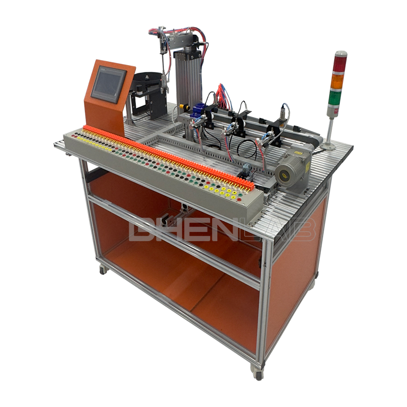
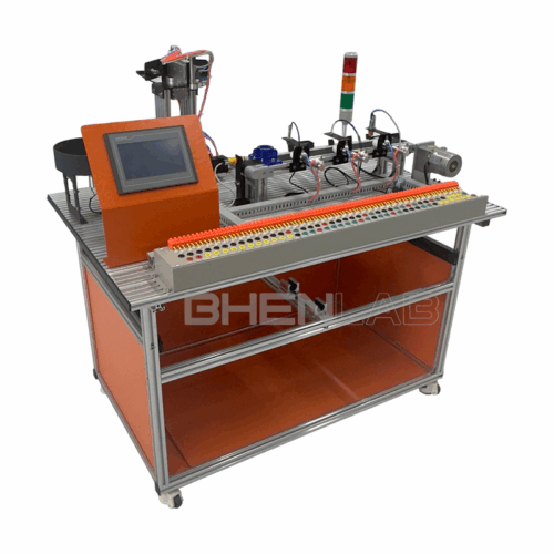
The device consists of some typical mechanical components and electrical control components, including workstations such as PLC module, input button module, power supply module, frequency converter module, wiring panel module, mechanical component module, etc. It is a mechatronics production line training and assessment device based on modern industrial equipment as the prototype. The overall structure adopts a detachable and open platform, which is used for training courses such as electrical circuit connection and mechanical component assembly. It can assemble existing mechanical components into different production processes, and can also add other modules to the device for expansion. The modules adopt standardized interfaces with good interchangeability, which can flexibly meet various teaching requirements.
II. Main Features:
1.Professionalism: The entire training device covers various technologies involved in mechatronics professional learning, such as motor drive, pneumatics, PLC (Programmable Logic Controller), sensors, etc. It solves the problem that students cannot operate and train on the actual production line. Instructors can conduct different levels of teaching and training for students on a series of topics from design, assembly, programming, debugging to problem inspection and maintenance.
2.Flexibility: The modules of the entire training device are independent of each other, each module has independent control, and the overall structure adopts a detachable and open platform for training courses such as electrical circuit connection and mechanical component assembly, which can accommodate more students to learn at the same time.
3.Openness: The PLC module I/O terminals, frequency converter terminals, connection terminals between common modules and PLC, sensors, button switches, indicator lights and other terminals of the experimental device are all open, and are connected by sheathed socket wires. It can carry out training on electrical circuit control, electrical circuit design and other contents.
4.Safety: The system has various protection functions such as short-circuit protection, emergency stop protection, limit protection, intelligent protection, etc., which can ensure personal and equipment safety.
5.Modular Concept: From different modules to work units, and from individual work units to the entire system, each work unit has a flexible combination mode.
III. Detailed Description of Functional Modules
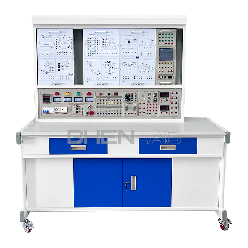
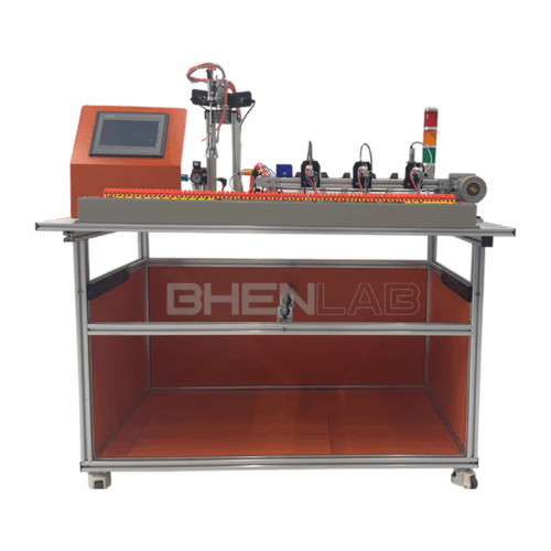
1. Training Platform
The whole is made of aluminum alloy with a size of approximately 1200x800x800. All industrial aluminum profiles are treated with bright surface oxidation. The panel of the electrical control screen is made of 2mm thick aluminum, with oxidation coloring treatment on the surface, which will never fade, and the lines and marks are clear.
2. PLC System
It adopts the new Mitsubishi FX3U series PLC with 48-point I/O relay output, and all PLC corresponding ports are led out to the panel.
3. Frequency Converter
It adopts a 380V AC frequency converter, Mitsubishi FR-E740 series, 0.75KW, and all terminals of the frequency converter are led out to the electrical panel.
4. Touch Screen
Kunlun Tongtai, 7-inch color, 6500 colors, synchronous communication with PLC.
5. Electrical Panel Module
It integrates 10 channels of buttons, and all button contacts are led to the panel. It is equipped with 24V power interface, indicator lights, power switch, emergency stop button, two sets of DC relays, etc. All terminals of electrical components such as contacts and coil terminals are led out to the panel.
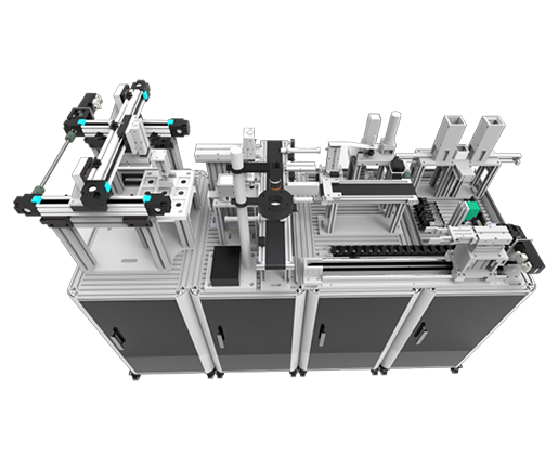
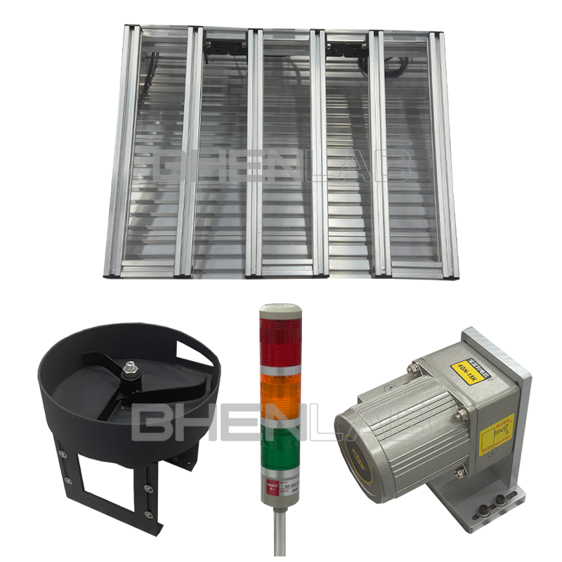
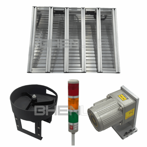
6. Feeding Mechanism
- Discharging Turntable: There are three kinds of materials in the turntable: one kind of metal material, one kind of black plastic material, and one kind of white plastic material.
- Material Chute: The discharging turntable rotates, and the materials are pushed towards the feeding port, and then the materials fall onto the blanking table along the chute from the feeding port.
- Drive Motor: The motor adopts a 24V DC deceleration motor with a speed of 10r/min and a torque of 30kg/cm, which is used to drive the discharging turntable to rotate.
- Material Detection: The material detection is a photoelectric diffuse reflection sensor. It mainly provides an input signal to the PLC. If there is material on the blanking table, the manipulator starts to act. If during operation, the photoelectric sensor does not detect the material and keeps this state for 6 seconds, the system will stop and alarm, and the red alarm light will start to flash.
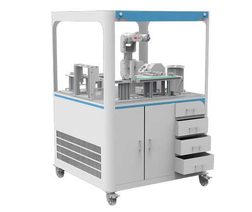
7. Manipulator Handling Mechanism
The entire handling mechanism can complete four-degree-of-freedom movements: arm extension and retraction, arm rotation, gripper up and down, and gripper clamping and loosening.
- Gripper Lifting Cylinder: The lifting cylinder is controlled by a two-way electric control valve, and the cylinder can be positioned arbitrarily when extending and retracting.
- Magnetic Sensor: It is used to detect whether the cylinder is in the extended or retracted position. (Note: The red wire is connected to “+”, and the black wire is connected to “-“)
- Gripper: Clamp or release materials.
- Gripper Sensor: The gripping of materials is controlled by a two-way electric control valve. When the two-way electric control valve is energized, the gripper clamps, the gripper sensor outputs a signal, and the indicator light is on. When the other end of the two-way electric control valve is energized, the gripper releases.
- Rotary Cylinder: Controls the left and right rotation of the mechanical arm, which is controlled by a two-way electric control valve.
- Proximity Sensor: Detection of the mechanical arm’s left and right rotation in place. When the left or right rotation is in place, the proximity sensor outputs a signal. (Note: The brown wire is connected to “+”, the blue wire is connected to “-“, and the black wire is connected to the output)
- Double-Rod Cylinder: The mechanical arm extends and retracts, controlled by a two-way electric control valve. The cylinder is equipped with two magnetic sensors to detect the extended or retracted position of the cylinder. (Note: The red wire is connected to “+”, and the black wire is connected to “-“)
- Buffer: When the rotary cylinder rotates left and right at high speed to the position, it plays a role of buffering and decelerating to keep the cylinder in place smoothly.
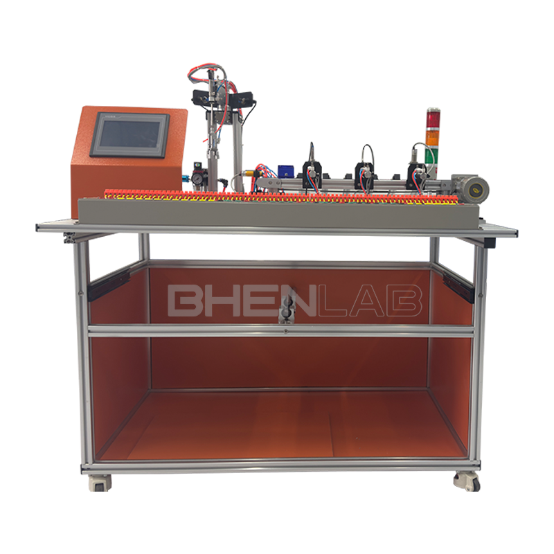
8. Material Conveying and Sorting Mechanism into the Warehouse
- Blanking Photoelectric Sensor: Detect whether there is material on the conveyor belt and give a signal to the PLC. When there is material, the frequency converter starts to control the motor to drive the conveyor belt to work. When there is no material, it stops after a 12-second delay. (Note: The brown wire is connected to “+”, the blue wire is connected to “-“, and the black wire is connected to the output)
- Blanking Hole: Material blanking hole.
- Metal Silo: For placing metal materials.
- Black Plastic Silo: For placing black plastic materials.
- White Plastic Silo: For placing white plastic materials.
- Inductive Sensor: Detect metal materials. (Note: The brown wire is connected to “+”, the blue wire is connected to “-“, and the black wire is connected to the output)
- Photoelectric Sensor: Detect black plastic materials. (Note: The brown wire is connected to “+”, the blue wire is connected to “-“, and the black wire is connected to the output)
- Capacitive Sensor: Used to detect white plastic materials. (Note: The brown wire is connected to “+”, the blue wire is connected to “-“, and the black wire is connected to the output)
- Three-Phase Asynchronous Motor: Driven by a frequency converter to drive the conveyor belt to rotate.
- Pushing Cylinder 1: Push metal materials into the silo, controlled by a one-way electric control valve.
- Pushing Cylinder 2: Push black plastic materials into the silo, controlled by a one-way electric control valve.
- Pushing Cylinder 3: Push white plastic materials into the silo, controlled by a one-way electric control valve.
9. Electrical Control Module Wiring
All modules can be used in combination with other working modules independently to achieve different combinations and meet different functional combination requirements. The connection mode of the electrical components of all working modules is: <Working Module> →→ <Component Interface> →→ <Collective Wiring Terminal> →→ <Desktop Open Port Board> →→ <PLC Open Interface>. Each component terminal of each working module and the corresponding each wiring port are clearly labeled. When connected to the <Desktop Open Port Board>, external open terminals are used, so that each connecting wire led from the collective wiring terminal can be easily connected to and replaced on the <Desktop Open Panel>, thus making the relatively complex lines of the whole system simple, clear and with good flexibility and openness. The system control line is connected from the <PLC Open Interface> to the <Desktop Open Port Board> through connecting wires, which enables free selection of ports when connecting the PLC to the components on the working module.
IV. Training Projects
The device provides a teaching and training platform for comprehensive application design, and the training content involves multi-disciplinary knowledge of mechanical, electrical, hydraulic and pneumatic integration majors.
1. Sensor Training
The sensors used in the system include inductive, photoelectric, electromagnetic, etc., each with its own characteristics and playing different roles to make the system work reliably and stably. Students can strengthen their perceptual understanding of these sensors by learning the working characteristics, missions and conditions of each workstation, and then combine with the teacher’s explanation, analysis and demonstration of the working principle of the sensors, so that students can quickly receive the relevant knowledge of the sensors and finally rise to the application level.
2. Pneumatic Technology Training
A large number of pneumatic components are used in the system, including various electric control valves, various cylinders, pneumatic clamps, filter regulators, throttle valves, etc. Combined with the actual typical application of the system and the actual application of each pneumatic component, students can learn the working principle and application occasions of each pneumatic component independently, including how these pneumatic components cooperate to carry out optimal design and application.
3. PLC Technology Training
With the open PLC control mode, each student can have the opportunity to disassemble, debug, connect electrical appliances, program PLC, etc. by themselves, which plays a good role in mobilizing students’ enthusiasm and interests, and provides a good training platform for students to learn PLC and apply PLC flexibly.
4. Electrical Control System Training
The electric control part is designed in accordance with industrial standards and habits, and all design drawings and instructions are provided as attachments. Students can learn circuit schematic analysis, PLC I/O address checking and new equipment circuit connection analysis methods on this device.
5. Mechanical System Installation and Debugging Training
The training device can be used to disassemble all or part of the mechanical parts, then reassemble them according to the requirements, and debug them until the system can work normally and reliably, which is of great help to improve the practical ability of students.
6. Motor Drive Technology Training
The training device involves a variety of motor drivers and controllers, which can be practically applied here. In addition, there are other motors in the system. Students will understand and recognize the characteristics, driving modes and applications of various motors.
7. System Maintenance and Fault Detection Technology Training
This part of the training focuses on introducing the contents and methods of daily maintenance of mechatronics systems, as well as the methods of analyzing and eliminating common faults of the system.
8. Computer Configuration Technology Training
With the increasing requirements for industrial automation and the need for communication between a large number of control equipment and process monitoring devices, monitoring and data acquisition systems have received more and more attention. Mastering the upper computer monitoring technology is also a compulsory course for students. The system adopts the typical industrial control configuration monitoring software popular in China. Through learning this software, students can understand the basic structure of communication networks, the basic framework of configuration monitoring software, the basic use methods of configuration software, as well as the common problems and processing methods in actual engineering.
9. Pneumatic System Installation and Debugging Projects:
Using the single-rod cylinder, single-rod double-rod cylinder, rotary cylinder and other pneumatic actuators, single-control solenoid directional valves, double-control solenoid directional valves, magnetic switches and other pneumatic control components configured in the device, the following work tasks of pneumatic technology can be completed:
- Installation of pneumatic direction control circuit
- Installation of pneumatic speed control circuit
- Installation of swing control circuit
- Installation of pneumatic sequence control circuit
- Installation of pneumatic manipulator device
- Installation and debugging of pneumatic system
10. Installation of Electrical Control Circuit and PLC Program Writing Projects:
Using the PLC module, frequency converter module, command switches, sensors, etc. configured in the device, the following work tasks of PLC application technology can be completed:
- Connection of motor forward and reverse control circuit and writing of control program
- Connection of motor speed regulation control circuit and writing of control program
- Writing of pneumatic direction control program
- Writing of pneumatic sequence action control program
- Writing of pneumatic manipulator control program
- Writing of belt conveyor control program
- Writing of mechatronics equipment control program
- Writing of automatic production line control program
11. Mechatronic Equipment Installation and Debugging Projects:
Using the mechatronics equipment components, PLC module, frequency converter module, command switches, sensors, etc. configured in the device, the following work tasks of mechatronic equipment installation and mechatronics technology can be completed:
- Adjustment of coaxiality of transmission device
- Installation and adjustment of belt conveyor
- Installation and debugging of handling manipulator equipment
- Installation and debugging of object sorting equipment
- Installation and debugging of feeding equipment
- Installation and debugging of automatic production line equipment
12. Installation and Debugging Projects of Automatic Control System:
Using the mechatronics equipment components, PLC module, frequency converter module, command switches, sensors, etc. configured in the device, the following work tasks of mechatronic equipment installation and mechatronics technology can be completed:
- Installation and debugging of various sensors
- Automatic control of manipulator
- Automatic control of belt conveyor
- Automatic control of mechatronic equipment
- Installation and debugging of PLC control system
- Installation and debugging of automatic production line
13. For Assessment or Skill Training, the following vocational abilities can be examined:
- Assembly and adjustment ability of mechanical components
- Installation and debugging ability of electromechanical equipment
- Circuit installation ability
- Installation and debugging ability of pneumatic system
- Ability to write control programs for mechatronic equipment
- Installation and debugging ability of automatic control system
V. Features
The PLC module I/O terminals, frequency converter terminals, connection terminals between common modules and PLC of the training and assessment device are all connected with safety sockets, and wires with safety plugs are used for circuit connection; The circuits of each command switch, photoelectric switch, sensor and indicator element are connected through terminal blocks. The combination of plug-in wire connection circuit and terminal block connection circuit not only ensures the training, formation and consolidation of students’ basic skills, but also ensures the rapidity, safety and reliability of circuit connection.
VI. Configuration List
| Serial Number | Name | Main Components or Model, Specification | Quantity | Unit | Remarks |
| 1 | Training Desk | 1 | Piece | ||
| 2 | Touch Screen Module | 7-inch | 1 | Block | |
| 3 | Touch Screen Communication Cable | 1 | Root | ||
| 4 | Mitsubishi PLC Module | FX3U-48MR | 1 | Set | |
| 5 | Mitsubishi Programming Cable | 1 | Root | ||
| 6 | Frequency Converter Module | Mitsubishi | 1 | Set | |
| 7 | Power Supply Module | Aluminum panel | 1 | Block | |
| 8 | Control Function Module | Aluminum panel | 1 | Set | |
| 9 | Material Conveyor Components | 1 | Set | ||
| 10 | Pneumatic Manipulator Components | 1 | Set | ||
| 11 | Belt Conveyor Components | 1 | Set | ||
| 12 | Object Sorting Components | 1 | Set | ||
| 13 | Terminal Block Module | Terminal block and safety socket | 1 | Block | |
| 14 | Materials | 3 metal, 3 black nylon, 3 white nylon | 1 | Set | |
| 15 | Safety Plug Wire | 1 | Set | ||
| 16 | Air Pipe | Φ4\Φ6\Φ8 | 1 | Set | |
| 17 | Mitsubishi PLC Programming Software | GX Developer | 1 | Set | Copy version |
| 18 | Cart | 1 | Piece | ||
| 19 | Product Supporting CD | 1 | Set | ||
| 20 | Instruction Manual | 1 | Volume | ||
| 21 | Computer Cart | Industrial aluminum profile frame structure | 1 | Set | |
| 22 | Air Compressor | 0.6~0.8MPa (equipped according to the classroom) | 1 | Room |