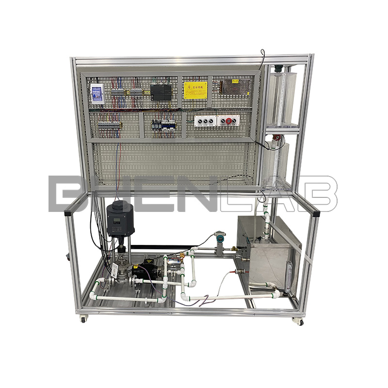


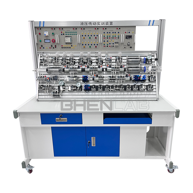
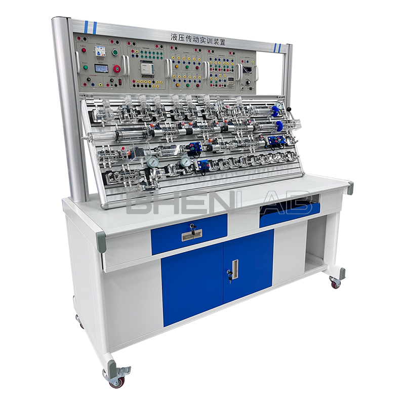
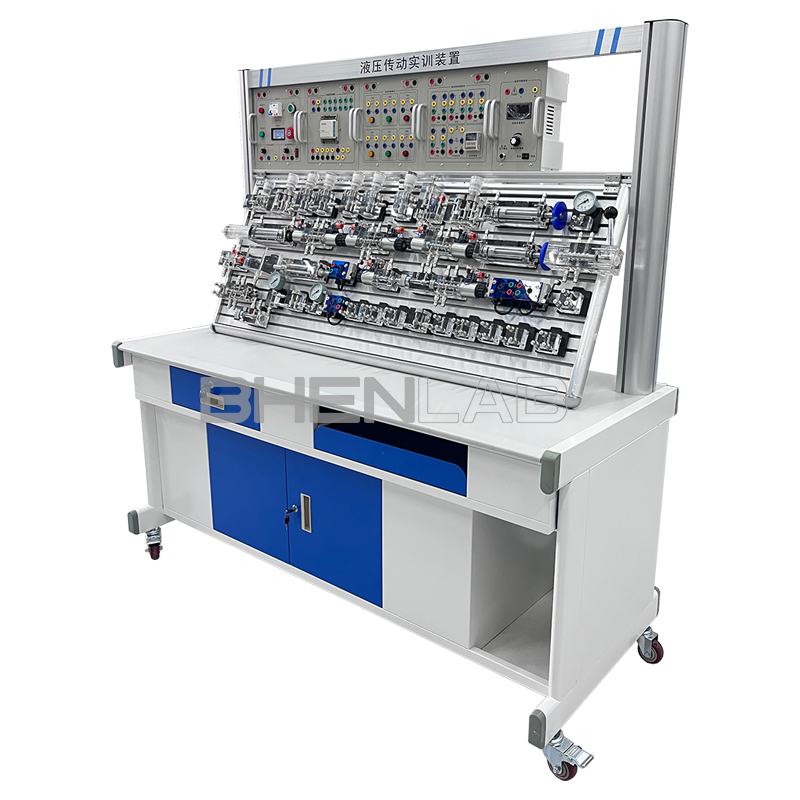
The transparent hydraulic transmission and PLC control training device is developed by our company in accordance with the teaching syllabus requirements of colleges and universities for electromechanical integration on pneumatic, electrical, and hydraulic control. Drawing on the advantages of our company’s hydraulic PLC control training equipment, it adopts an open comprehensive training platform structure. It has been continuously innovated and improved after extensively soliciting opinions from experts, professors, and teachers. It is currently an ideal comprehensive training equipment for hydraulic transmission control technology with PLC control. The training enables students to intuitively and perceptually compare and understand the characteristics, features, advantages, and disadvantages of electrical, hydraulic, and manual control respectively.
I. Main Technical Parameters
- Power supply: AC220V with a tolerance of ±10%, 50Hz;
- DC power supply: input AC220V, output DC24V/3A
- Device capacity: ≤1kVA;
- Operating environment temperature: -5℃ ~ 40℃;
- Operating humidity: ≤90% (at 40℃);
- Overall dimensions: 1700mm × 700mm × 1730mm
- Hydraulic pump station:
(1) System rated pressure: 0.8MPa;
(2) One set of quantitative gear pump and motor: adopting inner shaft integrated installation, with compact structure and low noise; Quantitative gear pump: rated flow 6L/min, pressure 2.5MPa; Motor: power 250W, speed regulation range 0 – 1500r/min, overall dimensions: 630mm × 380mm × 500mm. - Oil tank: hectare volume 45L; equipped with oil temperature and liquid level gauge, filter, air filter, shock – resistant pressure gauge, L – HL46 hydraulic oil;
- Hydraulic components:
Processed with transparent technology, the maximum working pressure is 2.0MPa. Each transparent hydraulic component is equipped with a base plate, which can be conveniently and randomly placed on the operation panel. The oil circuit connection adopts quick – change connectors, and transparent hoses are used, so that the flow of the oil circuit can be clearly and intuitively seen without oil leakage. - Electrical control unit:
(1) Power module: The power part is respectively equipped with a 380V voltmeter, a DC voltmeter, and an ammeter to monitor the input AC and DC power supplies and current indicators of the device. The start/stop button is mainly used to control whether the hydraulic pump station and air pump are energized. It is equipped with an emergency stop button, etc., to provide AC220V AC voltage and DC24V DC voltage in the electrical control circuit.
(2) PLC host module: The host selects Siemens 1214C host.
(3) Equipped with control modules: PLC input and output modules; relay modules; control button modules; time relay modules, etc.
Solenoid directional valve: DC24V, suction 3MPa
II. Main Features
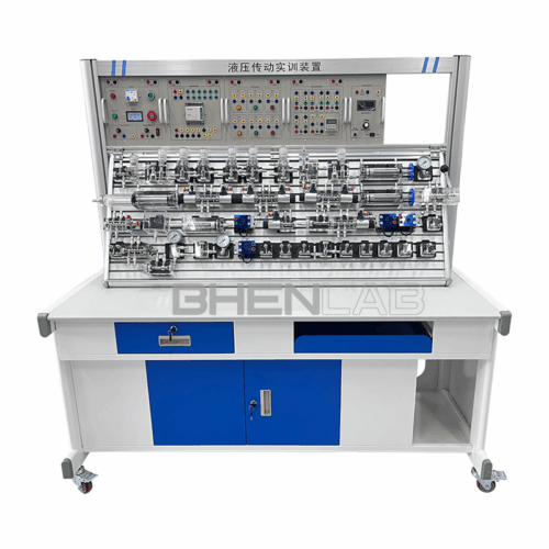
- The hydraulic PLC control training device is mainly composed of a training desk, a training platform, hydraulic components, electrical control devices, programmable logic controllers (PLC), and other devices.
- The training desk and training platform are of iron double – layer matte dense grain spray plastic structure, and the drawer of the training desk stores hydraulic components, etc.
- Equipped with all common hydraulic components: each hydraulic component is equipped with a mounting base plate, which can conveniently and randomly place the hydraulic components on the aluminum alloy profile panel (the panel is an aluminum alloy profile structure with a “T” groove). The oil circuit connection adopts quick – change connectors, which are convenient to disassemble and connect without oil leakage.
- The training components are made of transparent organic materials, which is convenient for understanding and mastering the structure, performance, and use of dozens of common hydraulic components. Master the working principle of dozens of basic circuits, and the experimental assembly circuit is fast and convenient.
- It integrates mechanical control, traditional relay control, advanced PLC automatic control, PLC programming, and monitoring technology to flexibly realize its functions.
- The experimental control unit can also adopt an independent relay control unit for electrical control. Through comparison, it highlights the superiority and advancement of PLC programmable control and deepens the understanding and mastery of PLC programmers.
III. Basic Training Circuits for Transparent Hydraulic PLC Control
- Commutation circuit with manual directional valve.
- Locking circuit with neutral function directional valve.
- Locking circuit with hydraulically controlled flat valve.
- Pressure setting circuit.
- Two – stage pressure control circuit.
- Pressure reducing circuit with pressure reducing valve.
- Boosting circuit with booster cylinder.
- Unloading circuit with H – type directional valve.
- Inlet throttle speed control circuit.
- Return oil throttle speed control circuit.
- Commutation speed control circuit of speed control gear pump.
- Composite speed control circuit composed of speed control gear pump and speed control valve.
- Speed switching circuit with short – circuited flow valve.
- Secondary feed circuit with series speed control valves.
- Secondary feed circuit with parallel speed control valves.
- Sequential action circuit with sequence valve.
- Sequential action circuit with pressure relay.
- Sequential action circuit controlled by travel switch.
- Sequential action circuit with travel directional valve.
- Synchronous circuit of series hydraulic cylinders.
- Commutation circuit controlled by pilot – operated relief valve.
- Pressure maintaining circuit with one – way valve.
- Pressure maintaining circuit with directional valve.
- Learning and use of PLC programming software.
- Communication between PLC and computer, online debugging and monitoring.
- Training of basic hydraulic circuits controlled by PLC (optimized control).
IV. Hydraulic Components

Two – position four – way solenoid directional valve
Hydraulically controlled check valve
d
Governor
Sequence valve
Two – position four – way travel directional valve
Pressure reducing valve
Throttle valve
Relief valve
Three – position five – way manual directional valve
Pressure relay
Travel switch, normally open, normally closed)
V. List of Transparent Hydraulic Training Devices
| Serial Number | Name | Model | Quantity | Remarks |
| 1 | Training desk | 1500×700×1750mm | 1 piece | |
| 2 | Training platform | 1 piece | ||
| 3 | PLC host module | Siemens 1214C | 1 piece | |
| 4 | Power module | 1 piece | ||
| 5 | Relay control module | 1 piece | ||
| 6 | Time relay module | 1 piece | ||
| 7 | Control button module | 1 piece | ||
| 8 | DC motor | Pump station | 1 piece | |
| 9 | Special speed regulation control module for DC motor | 1 piece | ||
| 10 | Digital tachometer and speed sensor | 1 piece | ||
| 11 | Gear oil pump (CB – B6) | 1 piece | ||
| 12 | Relief valve | 1 piece | ||
| 13 | Shock – resistant pressure gauge | 1 piece | ||
| 14 | Oil tank | 1 piece | ||
| 15 | Oil suction filter | 1 piece | ||
| 16 | Air filter | 1 piece | ||
| 17 | Oil temperature and liquid level gauge | 1 piece | ||
| 18 | Double – acting oil cylinder (with stroke stopper) | Transparent component | 2 pieces | |
| 19 | Two – position two – way solenoid directional valve | Transparent component | 1 piece | |
| 20 | Two – position four – way solenoid directional valve | Transparent component | 2 pieces | |
| 21 | Three – position four – way solenoid directional valve (O type) | Transparent component | 1 piece | |
| 22 | Three – position four – way solenoid directional valve (H type) | Transparent component | 1 piece | |
| 23 | Three – position four – way solenoid directional valve (M type) | Transparent component | 1 piece | |
| 24 | Spring return oil cylinder | Transparent component | 1 piece | |
| 25 | Booster cylinder | Transparent component | 1 piece | |
| 26 | Auxiliary oil tank | Transparent component | 1 piece | |
| 27 | Check valve | Transparent component | 2 pieces | |
| 28 | Hydraulically controlled check valve | Transparent component | 2 pieces | |
| 29 | Relief valve (direct – acting type) | Transparent component | 2 pieces | |
| 30 | Relief valve (pilot – operated type) | Transparent component | 1 piece | |
| 31 | Throttle valve (direct – acting type) | Transparent component | 1 piece | |
| 32 | Speed control valve | Transparent component | 2 pieces | |
| 33 | Sequence valve | Transparent component | 2 pieces | |
| 34 | Pressure reducing valve | Transparent component | 1 piece | |
| 35 | Two – position four – way travel directional valve | Transparent component | 1 piece | |
| 36 | Three – position five – way manual directional valve | Transparent component | 1 piece | |
| 37 | Pressure relay | Transparent component | 1 piece | |
| 38 | Pressure gauge | Transparent component | 3 pieces | |
| 39 | Three – way joint | Transparent component | 7 pieces | |
| 40 | Four – way joint | Transparent component | 3 pieces | |
| 41 | Travel switch | 4 pieces | ||
| 42 | Transparent hydraulic hose | 20 meters | ||
| 43 | Oil pan | 1 piece | ||
| 44 | Hydraulic oil | L – HL46 | 15L | |
| 45 | Programming cable | Mitsubishi | 1 piece | |
| 46 | National standard power cord | 1 piece | ||
| 47 | Experimental wire | 1 package | ||
| 48 | Quick oil joint | 5 pieces | ||
| 78 | Toolbox | 1 piece | ||
| 79 | Hexagon socket wrench | 3 pieces | ||
| 80 | Screwdriver | 2 pieces | ||
| 81 | Scissors | 1 piece | ||
| 82 | Adjustable wrench | 1 piece | ||
| 83 | Needle – nose pliers | 1 piece | ||
| 84 | Hydraulic training manual | 1 volume | ||
| 85 | PLC programming software and program | CD | 1 disc |