

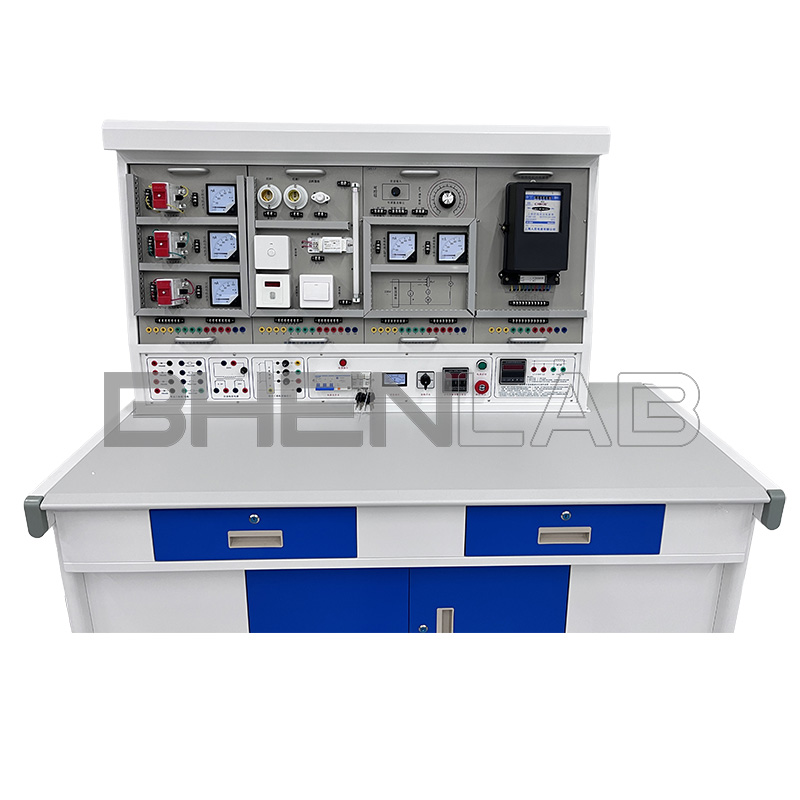
I. Overview
The “BOH-G206 Maintenance Electrician Electrical Control and Instrument Lighting Training Device” is a training device developed based on the training circuits listed in the junior and intermediate skill assessment content for maintenance electricians issued by the Ministry of Labor and Social Security. Through practical operations on this training device, users can quickly master the practical application technologies and operational skills of the course. This training device is not only suitable for students’ skill training but also an ideal equipment for skill assessment of junior and intermediate maintenance electricians in colleges and universities, technical schools, vocational schools, and labor vocational skill appraisal departments.
II. Features
- The components of the electrical control circuit are all mounted on mounting plates as hanging boards, which are easy to operate and replace, facilitating function expansion or new training development; the selection of operation contents is typical, practical, and scientific.
- The operation platform can be put into use only with a three-phase four-wire AC power supply.
- The control circuits for skill training and specially designed small motors can simulate various electrical drag systems in factories, and can meet the requirements of maintenance electricians for skill training in installation, commissioning, fault analysis, and troubleshooting.
- All components of the relay contact control circuit training are led to terminal blocks through wires. Students only need to connect wires on the terminals during wiring, which is beneficial to protect the components; during training, wires are routed through trunking for process wiring training.
- Electrical components such as contactors and thermal relays adopt well-known domestic and foreign brands to ensure the quality and performance of the equipment.
- Equipped with voltage-type leakage protectors and current-type leakage protectors to ensure the safety of operators; each power output has monitoring and short-circuit protection functions. In case of misoperation or short circuit caused by wrong wiring during training, the device can automatically protect, avoid burning fuses and damaging electrical appliances, and ensure the smooth progress of training.
- The control panel is also equipped with a timer and alarm recorder (service manager), providing a unified standard for the assessment of students’ experimental skills.
- The connection between the training circuit and the device power supply is through safety sockets and high-reliability sheathed structure pistol plugs, which is safe and fast.
- The device is equipped with a three-phase power output short-circuit soft cut-off protection function, which prevents damage to components due to short circuits caused by wrong wiring or misoperation during students’ training, and at the same time ensures the smooth progress of training and saves training costs.
III. Technical Performance
- Input voltage: three-phase four-wire 380V±10% 50Hz
- Working environment: ambient temperature range -5~+40℃, relative humidity <85% (25℃), altitude <4000m
- Device capacity: <1.5KVA
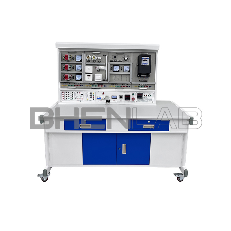
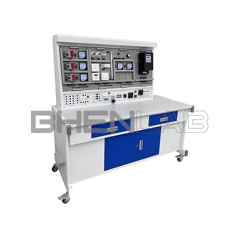
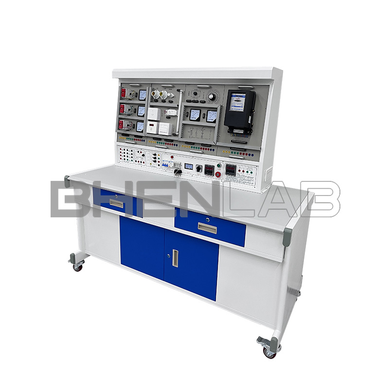
- Overall dimensions: 1600×700×1530mm
IV. Device Configuration
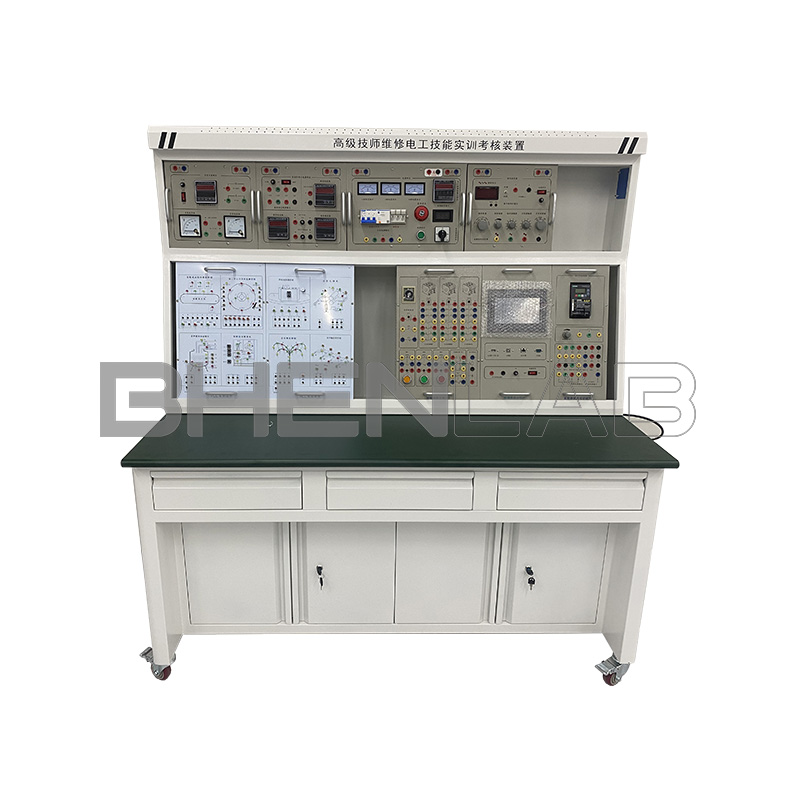
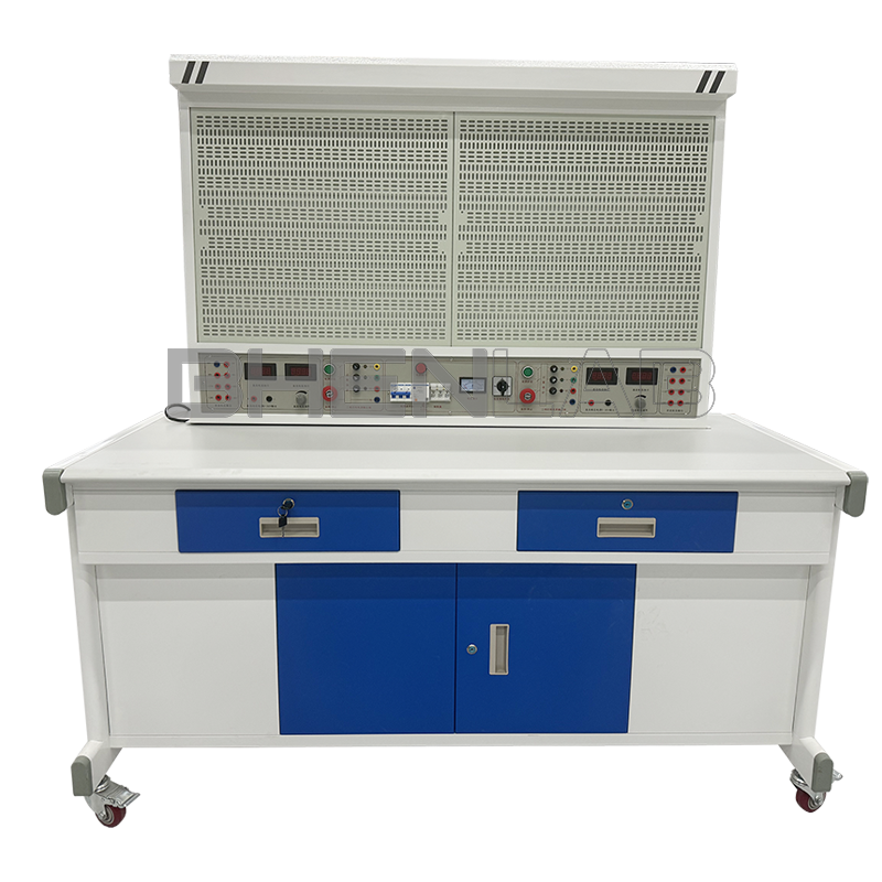
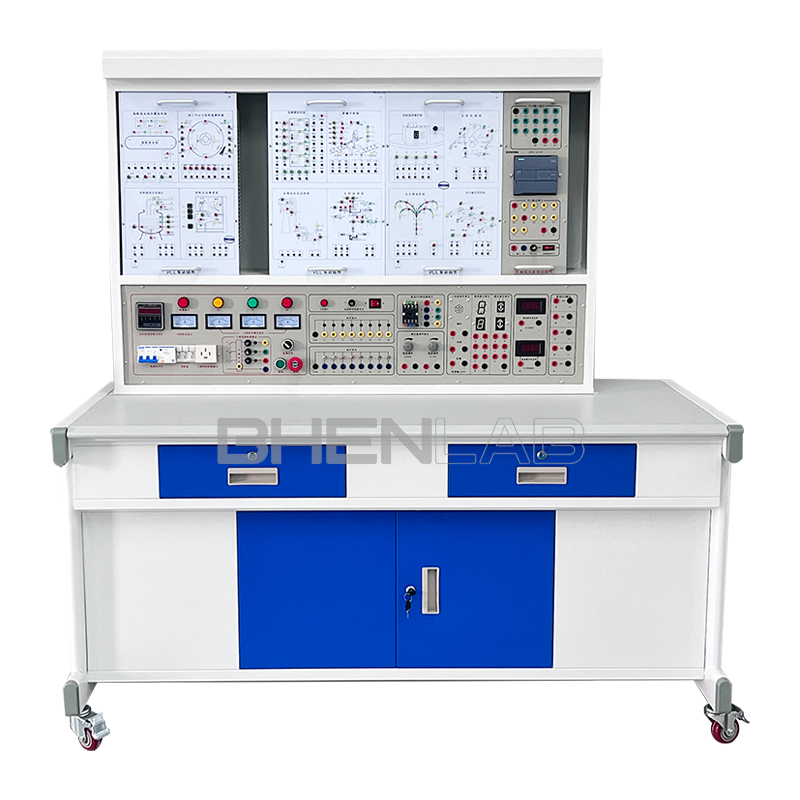
(I) DW02 Power Supply Control Panel
The control panel is of iron double-layer matte dense pattern spray structure with an aluminum panel.
Resources equipped on the main control function board:
Resources equipped on the main control function board:
- Three-phase four-wire power input, after passing through the leakage protector and main switch, the contactor is controlled to turn on and off through start and stop buttons, and is equipped with an emergency stop control button.
- There is one 450V pointer-type AC voltmeter on the control panel, which can observe three grid voltages through a band switch.
- Timer and alarm recorder (service manager), which is usually used as a clock, with functions of setting training time, timing alarm, and power cut-off; it can also automatically record the total number of leakage alarms and power short circuits caused by wiring or operation errors, providing a unified standard for the assessment of students’ training skills.
- AC low-voltage power supply: equipped with a transformer, with primary side 220V, secondary side 26V and 6.3V AC voltage. 6.3V is used for the power supply of signal indicator lights, and 26V is used for the AC power supply of the rectifier circuit in energy consumption braking.
- Four 5408 diodes, used for the rectifier circuit of energy consumption braking.
- Three 75Ω/75W resistors are used for motor step-down starting, and one 10Ω/25W resistor is used for asynchronous motor energy consumption braking.
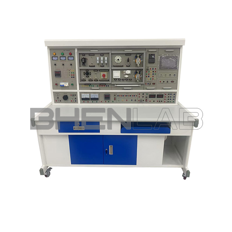
(II) Training Table
The training table is of iron double-layer matte dense pattern spray structure, with a fireproof, waterproof, and wear-resistant high-density board tabletop, a solid structure, and an elegant appearance. The table is equipped with two drawers (with locks) on each side and a cabinet, which can be used to place hanging parts and training items respectively.
V. Training Projects
- Single-phase start-stop control circuit
- Asynchronous motor inching control circuit
- Asynchronous motor two-location control circuit
- Asynchronous motor interlocking forward and reverse control circuit
- Double interlocking control circuit
- Automatic sequence control circuit
- Manual sequence starting
- Asynchronous motor star-delta control circuit
- Asynchronous motor energy consumption braking control circuit
- Button interlocking three-phase asynchronous motor forward and reverse control circuit
- Contactor interlocking three-phase asynchronous motor forward and reverse control circuit
- Double interlocking three-phase asynchronous motor forward and reverse control circuit
- One-way step-down starting and reverse connection braking control circuit
- Asynchronous motor reverse connection braking control circuit
- Automatic reciprocating control circuit
- Forward and reverse inching, starting control circuit
- Automatic reciprocating control circuit with inching function
- Asynchronous motor self-locking control circuit
- Asynchronous motor single-phase inching, starting control circuit
- Manual control circuit for stator series resistance step-down starting of three-phase asynchronous motor
- Automatic control circuit for stator series resistance step-down starting of three-phase asynchronous motor
- Contactor-controlled two-speed motor control circuit
- Time relay-controlled two-speed motor control circuit
- C620-1 lathe control circuit
- Electric hoist control circuit
- Y3150 gear hobbing machine control circuit
- Electric hoist circuit
- Z3040 radial drilling machine circuit
- CA6140 lathe circuit
- Starting of shunt-excited DC motor
- Speed regulation of shunt-excited DC motor
- Forward and reverse rotation of shunt-excited DC motor
- Braking of shunt-excited DC motor
- Socket and one switch control one lamp (incandescent lamp, fluorescent lamp + two-pole leakage switch)
- Two two-way switches control one lamp (incandescent lamp, fluorescent lamp + two-pole leakage switch)
- Three switches control one lamp (incandescent lamp, fluorescent lamp + two-pole leakage switch)
- Wiring of fluorescent lamp circuit
- Wiring of sound-controlled switch controlling incandescent lamp circuit
- Wiring of touch delay switch controlling incandescent lamp circuit
- Wiring of human body induction switch controlling incandescent lamp circuit
- Direct wiring circuit of single-phase watt-hour meter
- Wiring circuit of single-phase watt-hour meter through current transformer
- Wiring circuit of voltmeter and ammeter
- Wiring of voltmeter measuring three-phase voltage with universal changeover switch
- Control circuit wiring of one current transformer used in single-phase circuit
- Three current transformers connected in star wiring circuit
- Three current transformers connected in delta wiring circuit
- Measuring circuit of three-phase power factor meter
- Wiring circuit of three-phase three-wire active watt-hour meter
- Wiring circuit of three-phase three-wire active watt-hour meter through current transformer
- Wiring circuit of three-phase four-wire active watt-hour meter
- Wiring circuit of three-phase four-wire reactive watt-hour meter through current transformer
- Wiring circuit of three-phase four-wire reactive watt-hour meter
- Wiring circuit of three-phase four-wire reactive watt-hour meter through current transformer
VI. Configuration of Training Component Hanging Boxes
The hanging boxes are installed with fuses, toggle switches, AC contactors, time relays, DC contactors, button switches, signal indicator lights, thermal relays, instruments, etc. All devices adopt well-known domestic and foreign brands. The wiring of various training components is carried out on terminal blocks, which avoids the loss of components caused by long-term screw disassembly on the devices themselves. Wires are routed through trunking for process wiring training. The connection between the training circuit and the device power supply is through safety sockets and high-reliability sheathed structure pistol plug connecting wires, which is safe and fast.
| 일련 번호 | Hanging Box Number | Name of Training Module | 수량 | 비고 |
|---|---|---|---|---|
| 1 | DW-01 | Maintenance Electrician Training Component (I) | 1 piece | The hanging board is equipped with thermal relays, AC contactors (380V), button indicators (6.3V), terminal blocks, etc. |
| 2 | DW-02 | Maintenance Electrician Training Component (II) | 1 piece | The hanging board is equipped with screw-type fuses, plug-in fuses, low-voltage circuit breakers, time relays, AC contactors, terminal blocks, etc. |
| 3 | DW-03 | Maintenance Electrician Training Component (III) | 1 piece | The hanging board is equipped with screw-type fuses, changeover switches, solenoid valves, cross switches, travel switches, etc. |
| 4 | DW-17 | Electrical Training Assessment Component (VI) | 1 piece | Provides DC motor working power supply, control links, and Ia, If indicators |
| 5 | DW-10 | Instrument Lighting Training Assessment Component (I) | 1 piece | Provides 1 two-pole leakage protector, 2 3P fuses, 1 knife switch, 1 single-phase watt-hour meter |
| 6 | DW-11 | Instrument Lighting Training Assessment Component (II) | 1 piece | Provides 2 screw lamp holders, 3 switch boxes, 1 ballast, 1 starter, 1 fluorescent lamp |
| 7 | DW-12 | Instrument Lighting Training Assessment Component (III) | 1 piece | Provides 3 AC ammeters, 3 current transformers |
| 8 | DW-13 | Instrument Lighting Training Assessment Component (IV) | 1 piece | Provides 1 AC voltmeter, 1 three-phase power factor meter, 1 voltage indicator changeover switch |
| 9 | DW-14 | Instrument Lighting Training Assessment Component (V) | 1 piece | Provides 1 three-phase three-wire active watt-hour meter |
| 10 | DW-15 | Instrument Lighting Training Assessment Component (VI) | 1 piece | Provides 1 three-phase four-wire active watt-hour meter |
| 11 | DW-16 | Instrument Lighting Training Assessment Component (VII) | 1 piece | Provides 1 three-phase four-wire reactive watt-hour meter |
| 12 | Three-phase squirrel-cage motor 380V/Y | 1 unit | ||
| 13 | Two-speed asynchronous motor 380V/YY/△ | 1 unit | ||
| 14 | Three-phase squirrel-cage motor 380V/△ | 1 unit | ||
| 15 | Shunt-excited DC motor 220V/200W |