


I. Overview
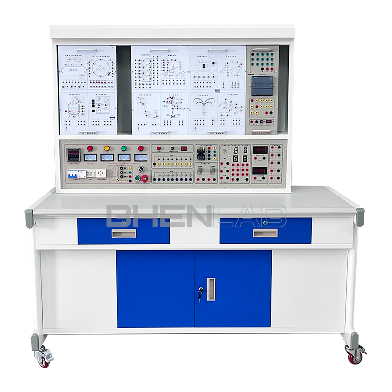
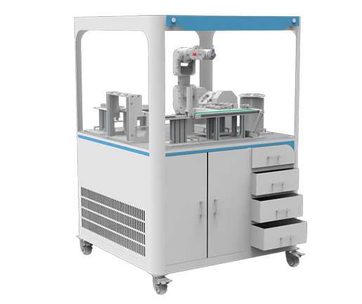
BOH-LYY01 Transparent Hydraulic Transmission and PLC Control Training Device is developed by our company according to the needs of colleges and universities’ mechatronics majors for carrying out hydraulic transmission demonstrations, basic circuits of multiple control modes (manual, relay, PLC) and configuration simulation training. It is suitable for the teaching and training needs of courses such as “Hydraulic Transmission” and “Hydraulic and Pneumatic Transmission” in mechanical and electrical majors of colleges and universities.
II. Device Features
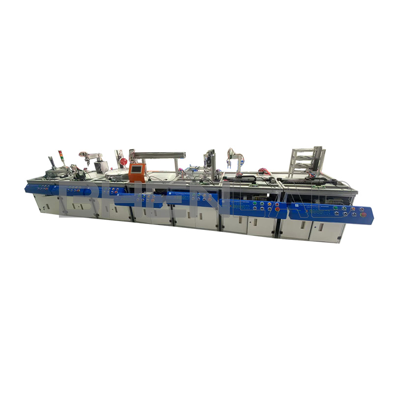
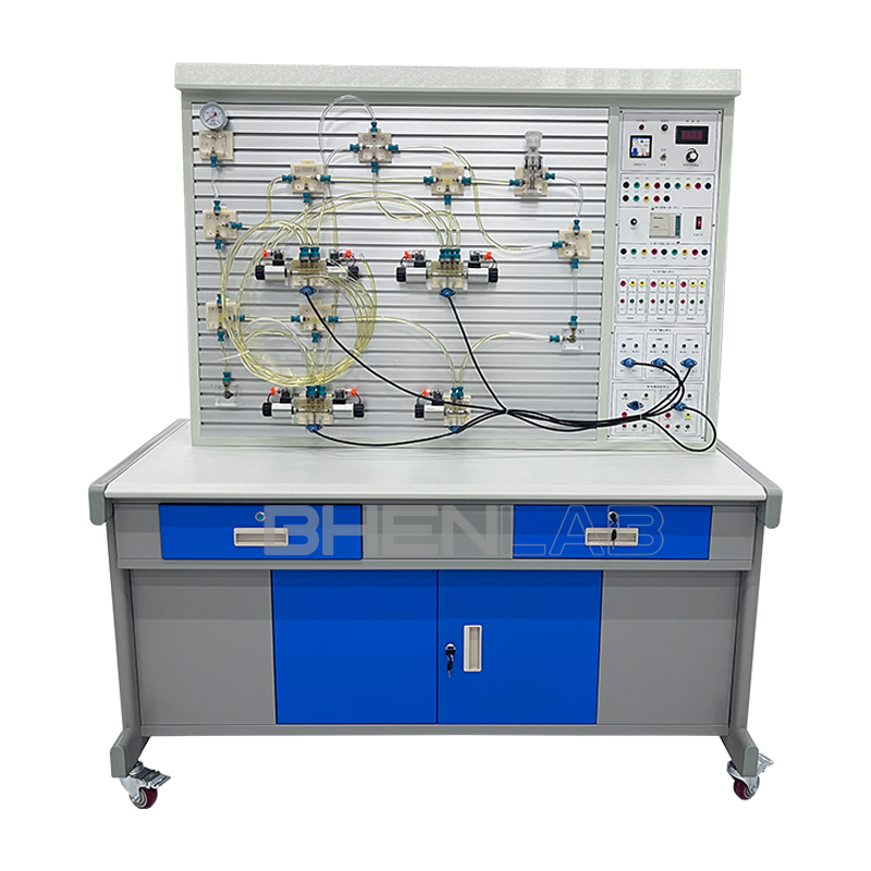
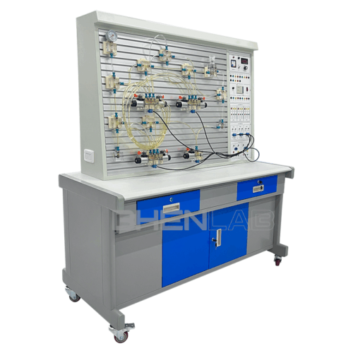
- The hydraulic PLC control training device is mainly composed of a training desk, a training platform, hydraulic components, electrical control devices, programmable logic controller (PLC) and other devices.
- The training desk and training platform adopt a double-layer iron matte dense-grain spray structure, with a ship-shaped leak-proof design. There is a component storage cabinet under the training desk.
- Equipped with all common hydraulic components: each hydraulic component is equipped with a mounting base plate, which can be conveniently and randomly placed on the aluminum alloy profile panel (the panel is an aluminum alloy profile structure with a “T” groove). The oil circuit is connected with quick-change joints, which are easy to disassemble and connect without oil leakage.
- The hydraulic circuit can be controlled manually, by relays or by PLC, with multiple control modes.
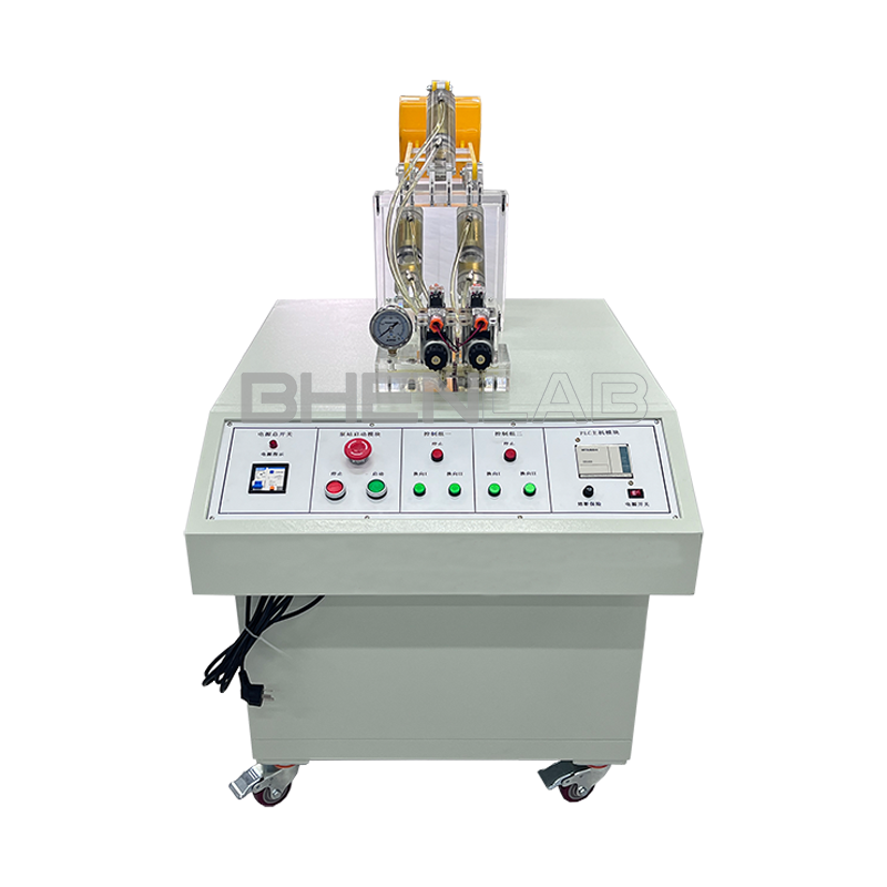
- The power supply part is equipped with a 380V voltmeter, a DC voltmeter and an ammeter to monitor the AC and DC input power and current indication of the device. The start/stop button is mainly used to control whether the hydraulic pump station is powered on. It is equipped with an emergency stop button, etc., to provide AC220V AC voltage and DC24V DC voltage in the electrical control circuit.
- Equipped with 8 DC +24V relays and 2 DC +24V time relays, all terminals of switch quantities (including coils) are led to the panel, and there is a corresponding indicator light when the coil is energized. It is also required to be equipped with 6 green self-reset button switches and 6 red self-locking button switches. All terminals of the button switches are led to the panel.
- It integrates mechanical control, traditional relay control, advanced PLC automatic control, PLC programming and monitoring technology, and can flexibly realize its functions.
- The experimental control unit can also adopt an independent relay control unit for electrical control. Through comparison, it highlights the superiority and advancement of PLC programmable control, and deepens the understanding and mastery of PLC programmers.
III. Technical Parameters
- Power input: 220V, cut off the power when the leakage current to the ground exceeds 30mA;
- DC power input: AC220V, output DC24V/3-5A with overload protection;
- Device capacity: ≤2kVA;
- Working environment temperature: -5℃~40℃;
- Working humidity: ≤90% (at 40℃);
- Overall dimensions: 1510mm×700mm×1750mm;
- Hydraulic pump station:
(1) System rated pressure: 0.8MPa;
(2) 1 set of quantitative gear pump-motor: Adopting inner shaft integrated installation, with a compact structure and low noise; Quantitative gear pump: rated flow 6L/min, pressure 2.5MPa; Motor: power 250W, speed regulation range 0-1500r/min, overall dimensions: 630mm×380mm×500mm.
(3) Oil tank: volume 45L; Equipped with oil temperature and level gauge, filter, air filter, shock-resistant pressure gauge, and L-HL46 hydraulic oil; - Hydraulic components:
Made of transparent technology, with a maximum working pressure of 2.0MPa. Each transparent hydraulic component is equipped with a base plate, which can be conveniently and randomly placed on the operation panel. The oil circuit is connected with quick-change joints, and transparent hoses are used, so that the flow of the oil circuit can be clearly and intuitively seen without oil leakage. - Electrical control unit:
(1) Power module: The power supply part is equipped with a 380V voltmeter, a DC voltmeter and an ammeter to monitor the input AC and DC power and current indication of the device. The start/stop button is mainly used to control whether the hydraulic pump station and air pump are powered on. It is equipped with an emergency stop button, etc., to provide AC220V AC voltage and DC24V DC voltage in the electrical control circuit.
(2) PLC host module: The host uses Mitsubishi FX5U-32MR host, with 16 channels of DC input / 16 channels of relay output.
(3) Equipped with control modules: PLC input and output modules; relay modules; control button modules; time relay modules, etc. - Solenoid directional valve: DC24V, suction 3MPa.
IV. Basic Training Circuits for Transparent Hydraulic PLC Control
- Commutation circuit with manual directional valve.
- Locking circuit with neutral function directional valve.
- Locking circuit with hydraulically controlled flat valve.
- Pressure setting circuit.
- Two-stage pressure control circuit.
- Pressure reducing circuit with pressure reducing valve.
- Boosting circuit with booster cylinder.
- Unloading circuit with H-type directional valve.
- Inlet throttling speed control circuit.
- Return oil throttling speed control circuit.
- Commutation speed control circuit of speed control gear pump.
- Composite speed control circuit composed of speed control gear pump and speed control valve.
- Speed switching circuit with short-circuited flow valve.
- Secondary feed circuit with series speed control valves.
- Secondary feed circuit with parallel speed control valves.
- Sequential action circuit with sequence valve.
- Sequential action circuit with pressure relay.
- Sequential action circuit controlled by travel switch.
- Sequential action circuit with travel directional valve.
- Synchronous circuit of series hydraulic cylinders.
- Commutation circuit controlled by pilot-operated relief valve.
- Pressure maintaining circuit with check valve.
- Pressure maintaining circuit with directional valve.
- Learning and use of PLC programming software.
- Communication between PLC and computer, online debugging and monitoring.
- Training of basic hydraulic circuits controlled by PLC (optimized control).
V. Hydraulic Components
Booster cylinder, double-acting cylinder, spring return cylinder, three-position four-way solenoid directional valve (OHMPY), two-position four-way solenoid directional valve, hydraulically controlled check valve, governor, sequence valve, two-position four-way travel directional valve, pressure reducing valve, throttle valve, relief valve, three-position five-way manual directional valve, pressure relay, travel switch (normally open, normally closed).
VI. List of Transparent Hydraulic Training Devices
| Número de serie | Name | Model | Cantidad | Remarks |
| 1 | Training Desk | 1500×700×1800mm | 1 piece | |
| 2 | Training Platform | 1 set | ||
| 3 | PLC Host Module | Mitsubishi FX5U-32MR | 1 piece | |
| 4 | Power Module | 1 piece | ||
| 5 | Relay Control Module | 1 piece | ||
| 6 | Time Relay Module | 1 piece | ||
| 7 | Control Button Module | 1 piece | ||
| 8 | DC Motor | Pump station | 1 set | |
| 9 | Special Speed Control Module for DC Motor | 1 piece | ||
| 10 | Digital Tachometer and Speed Sensor | 1 piece | ||
| 11 | Gear Oil Pump (CB-B6) | 1 piece | ||
| 12 | Relief Valve | 1 piece | ||
| 13 | Shock-Resistant Pressure Gauge | 1 piece | ||
| 14 | Oil Tank | 1 piece | ||
| 15 | Oil Suction Filter | 1 piece | ||
| 16 | Air Filter | 1 piece | ||
| 17 | Oil Temperature and Level Gauge | 1 piece | ||
| 18 | Double-Acting Cylinder (with stroke stop block) | Transparent component | 2 pieces | |
| 19 | Two-Position Two-Way Solenoid Directional Valve | Transparent component | 1 piece | |
| 20 | Two-Position Four-Way Solenoid Directional Valve | Transparent component | 2 pieces | |
| 21 | Three-Position Four-Way Solenoid Directional Valve (Type O) | Transparent component | 1 piece | |
| 22 | Three-Position Four-Way Solenoid Directional Valve (Type H) | Transparent component | 1 piece | |
| 23 | Three-Position Four-Way Solenoid Directional Valve (Type M) | Transparent component | 1 piece | |
| 24 | Spring Return Cylinder | Transparent component | 1 piece | |
| 25 | Booster Cylinder | Transparent component | 1 piece | |
| 26 | Auxiliary Oil Tank | Transparent component | 1 piece | |
| 27 | Check Valve | Transparent component | 2 pieces | |
| 28 | Hydraulically Controlled Check Valve | Transparent component | 2 pieces | |
| 29 | Relief Valve (Direct-Acting Type) | Transparent component | 2 pieces | |
| 30 | Relief Valve (Pilot-Operated Type) | Transparent component | 1 piece | |
| 31 | Throttle Valve (Direct-Acting Type) | Transparent component | 1 piece | |
| 32 | Speed Control Valve | Transparent component | 2 pieces | |
| 33 | Sequence Valve | Transparent component | 2 pieces | |
| 34 | Pressure Reducing Valve | Transparent component | 1 piece | |
| 35 | Two-Position Four-Way Travel Directional Valve | Transparent component | 1 piece | |
| 36 | Three-Position Five-Way Manual Directional Valve | Transparent component | 1 piece | |
| 37 | Pressure Relay | Transparent component | 1 piece | |
| 38 | Pressure Gauge | Transparent component | 3 pieces | |
| 39 | Three-Way Joint | Transparent component | 7 pieces | |
| 40 | Four-Way Joint | Transparent component | 3 pieces | |
| 41 | Travel Switch | 4 pieces | ||
| 42 | Transparent Hydraulic Hose | 20 meters | ||
| 43 | Oil Pan | 1 piece | ||
| 44 | Hydraulic Oil | L-HL46 | 15L | |
| 45 | Programming Cable | Mitsubishi | 1 piece | |
| 46 | National Standard Power Cord | 1 piece | ||
| 47 | Experimental Wire | 1 package | ||
| 48 | Quick Oil Joint | 5 pieces | ||
| 78 | Toolbox | 1 piece | ||
| 79 | Hexagon Socket Wrench | 3 pieces | ||
| 80 | Screwdriver | 2 pieces | ||
| 81 | Scissors | 1 piece | ||
| 82 | Adjustable Wrench | 1 piece | ||
| 83 | Needle-Nose Pliers | 1 piece | ||
| 84 | Hydraulic Training Manual | 1 volume | ||
| 85 | PLC Programming Software and Programs | CD | 1 disc |