


I. Overview
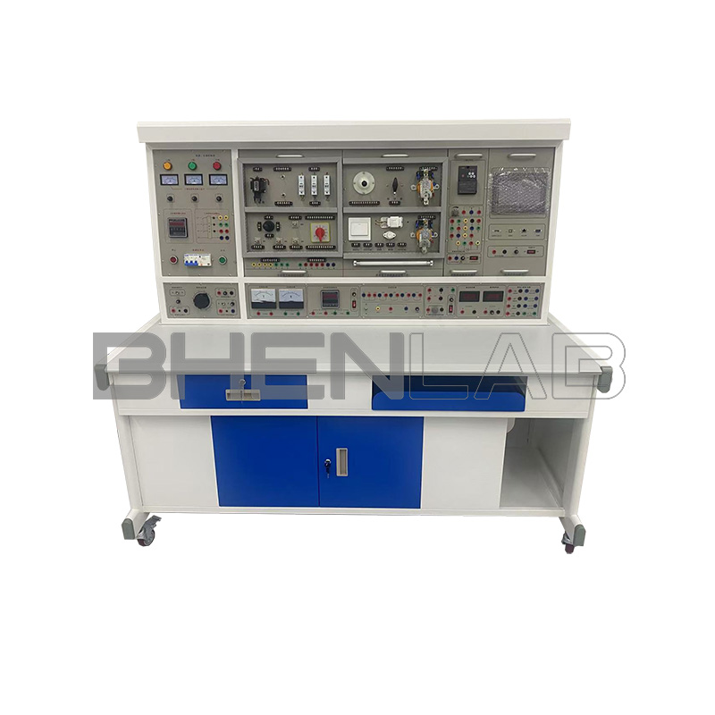
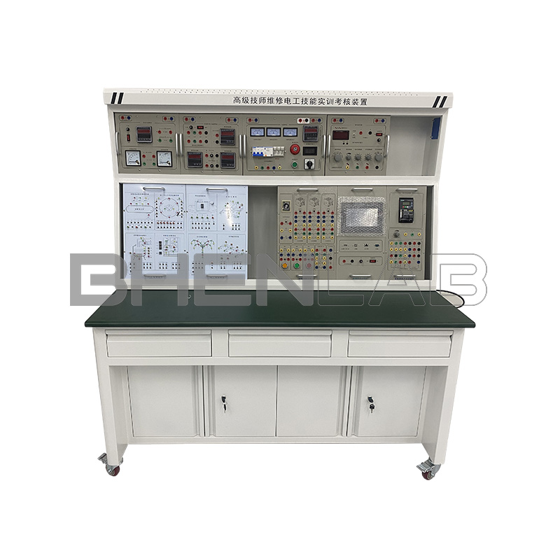
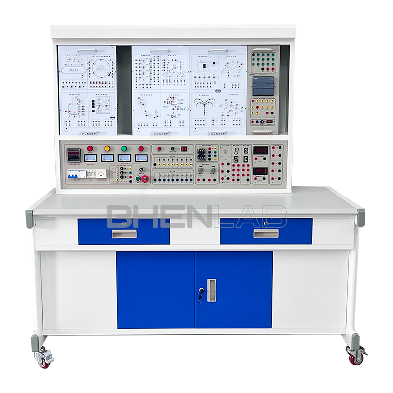
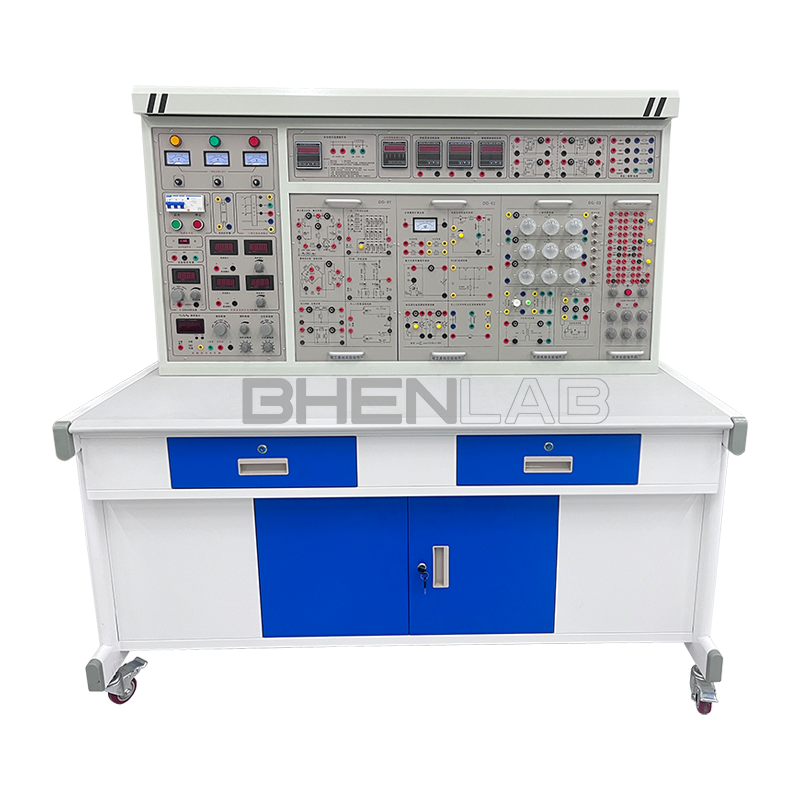
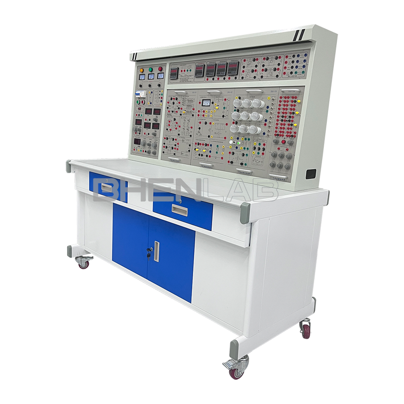
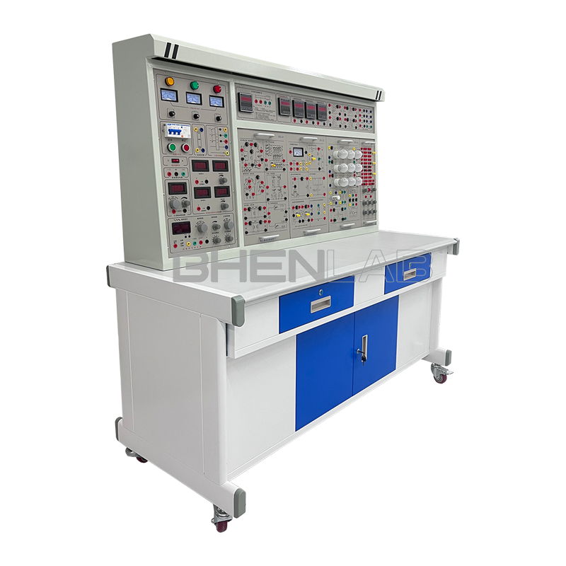
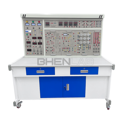
The BOH-DGT high-performance electrical, electronic and electrical traction experimental device absorbs the advantages of advanced teaching instruments at home and abroad, fully considers the current situation and future development trend of laboratories, and has made innovations in performance and structure. It adopts a hanging box structure, which is concise, clear, reasonably arranged, and convenient and flexible to use. The experimental instruments are fully digitally displayed with high precision. Reliable protection is provided for the power supplies and instruments involved in the experiment, and a reliable personal safety protection system is set up. The experimental device has superior performance and is the best choice for laboratory construction in colleges and universities.
Purpose: Suitable for experimental teaching of courses such as “Fundamentals of Electrical Engineering”, “Electrical Engineering”, “Digital Electronics”, “Analog Electronics”, “Motor Engineering”, “Motor and Electrical Drive”, “Electrical Control”, “Relay Contact Control” in colleges and universities. It can also expand experimental contents such as “Programmable Controller” and “Motor Frequency Conversion Control”.
II. Features:
- Strong comprehensiveness: Integrates all experimental projects of electrical basic courses in various domestic schools.
- Strong adaptability: The depth and breadth of experiments can be flexibly adjusted as needed, and popularization and improvement can be organically combined according to the teaching process. The device has a modular structure, which is convenient to replace, and adding components can expand functions or develop new experiments.
- Strong integrity: It is fully equipped with instruments, special power supplies, and special wires for experimental connections. The performance, accuracy, and specifications of the instruments are all matched closely according to the needs of the experiment.
- Strong consistency: The experimental devices are reasonably selected and fully matched, so that the results of multiple groups of experiments have good consistency, which is convenient for teachers to organize and guide experimental teaching.
- Strong intuitiveness: The device adopts a structure combining the whole and hanging parts. The power configuration and instruments are clear at a glance. Each experimental hanging box has clear tasks, and the operation and maintenance are simple.
III. Technical Indicators and Instructions:
- Overall dimensions: 160x70x143cm
- Working power supply: AC three-phase four-wire 380±5% 50Hz
- Input power: <1.5KVA
- Output AC power supply: three-phase four-wire 380V.
- Personal safety protection functions: current-type leakage protection, voltage-type leakage protection and anti-electric shock experimental wires.
- DC regulated power supply: two groups of 0-30V continuously adjustable, automatic relay shifting, digital meter display, automatic overload protection, indication and automatic recovery functions.
- Constant current source: 0-200mA continuously adjustable, digital meter display, open circuit protection.
- Timer and alarm recorder: The power control screen is equipped with a timer and alarm recorder, which has functions such as setting experiment time and recording the number of alarms.
- Function signal generator:
- Waveforms: sine wave, triangular wave, square wave.
- Frequency range: 5Hz-550KHz, continuously adjustable in sections.
- Distortion degree of sine wave: less than 1% at 10Hz-100KHz.
- Output amplitude: sine wave greater than 0-14Vp-p.
Frequency meter: The measurement range is 1Hz to 8MHz, with six-digit LED digital tube display, gate time base 1S, sensitivity 35mV. Switch (internal measurement/external measurement) conversion.- DC digital voltmeter: made of microprocessor; 0.5-level accuracy; measurement range: 0-300V.
- DC digital milliammeter: made of microprocessor; 0.5-level accuracy; measurement range: 0-500mA.
- DC digital ammeter: made of microprocessor; 0.5-level accuracy; measurement range: 0-5A.
- AC digital voltmeter: made of the latest professional MCU; accuracy 0.5 level, measurement range: 0-450V.
- AC digital ammeter: made of the latest professional MCU; accuracy 0.5 level, measurement range: 0-5A.
- Training connecting wires: According to the characteristics of different training projects, two different specifications of training connecting wires are provided. Both strong and weak currents use high-reliability sheathed structure with gun plug connecting wires (there is no possibility of electric shock). The inside is made of oxygen-free copper drawn into multiple strands as thin as hair to achieve ultra-soft purpose. The outer layer is covered with nitrile polyvinyl chloride insulation layer, which has the advantages of softness, high voltage resistance, high strength, anti-hardening, and good toughness. The plug is made of solid copper with beryllium-copper shrapnel, which is safe and reliable in contact; the two types of wires can only be matched with sockets of corresponding inner holes and cannot be mixed, which greatly improves the safety and rationality of the training.
- Experimental hanging boxes:
The front of the panel of the experimental hanging box is printed with schematic diagrams and symbols, and the corresponding components are welded on the back. The parts that need to be measured and observed are equipped with locking connectors, which are convenient, intuitive and reliable to use. The experimental circuit is designed in the form of unit circuits. Each unit circuit is based on a basic circuit, and then connects different components to the circuit parameters or combines different unit circuits to complete different experimental requirements.
(1) Electrical experiment hanging box 1
Equipped with RC series-parallel frequency selection network experimental circuit, Thevenin’s theorem/Norton’s theorem experimental circuit, RLC series resonance experimental circuit, Kirchhoff/superposition theorem experimental circuit, first-order and second-order experimental circuits, two-port network, reciprocity theorem experimental circuit. The front of the hanging box panel is printed with schematic diagrams and symbols, and the corresponding components are welded on the back, which is convenient, intuitive and reliable to use.
(2) Electrical experiment hanging box 2
Equipped with instrument range extension experimental circuit, circuit state trajectory observation experimental circuit, maximum power transmission condition determination experimental circuit, RC double T frequency selection network experimental circuit, voltage source and current source equivalent transformation experimental circuit, RLC component characteristics and AC parameter determination experimental circuit. The front of the hanging box panel is printed with schematic diagrams and symbols, and the corresponding components are welded on the back, which is convenient, intuitive and reliable to use.
(3) Electrical experiment hanging box 3
Equipped with light group (9 15W colored lights) experimental circuit, capacitor group, single-phase watt-hour meter, fluorescent lamp experimental circuit. Equipped with one mutual inductance experimental circuit (one each of large and small mutual inductance coils) and one iron core transformer (36V/220V, 50W).
(4) Component box
Equipped with several resistors, capacitors, diodes and other experimental components needed for the experiment, and a resistor box of 0-99999.9 ohm/2W.
(5) Controlled source and gyrator hanging box
Equipped with VCVS, VCCS, CCVS, CCCS controlled source experimental circuits, gyrator experimental circuits, and negative impedance converter experimental circuits.
(6) Analog electronic experiment hanging box
Equipped with power supply experimental circuit, operational amplifier experimental circuit, DC signal source, low-voltage AC power supply, resistors, capacitors, triodes and other experimental components; equipped with single-tube, multi-stage, negative feedback experimental modules, separate and integrated power amplifier experimental modules.
(7) Digital electronic experiment hanging box
Equipped with 8-bit logic level switches, 8-bit logic level indicators, four-digit decimal code setting displays, one common cathode nixie tube, two groups of dial switches, single pulse, several high-reliability round-foot integrated sockets (8P, 14P, 16P, 28P, 40P, etc.), and resistors, potentiometers, triodes, etc. needed for the experiment.
(8) Relay control experiment hanging box 1
Equipped with 3 AC contactors with power-on indication, 1 thermal relay, 1 time relay, 2 start-stop buttons, 3 fuse holders, and 1 three-phase switch.
(9) Relay control experiment hanging box 2
Equipped with 1 BK transformer. 1 AC contactor with power-on indication, 1 thermal relay, 2 start-stop buttons, 3 fuse holders, 1 three-phase switch. 1 set of rectifier bridges. 3 indicator lights.
IV. Configuration of Experimental Equipment
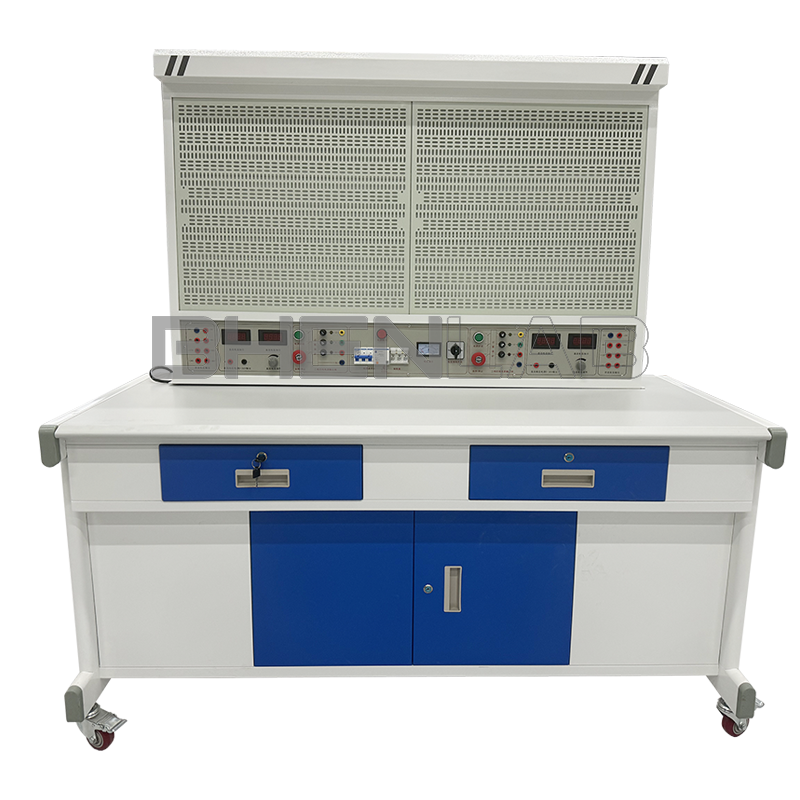
- Experimental desk: all-steel structure, steel spray coating, wear-resistant and fireproof panel, with drawers and cabinets for storing tools, accessories, etc.
- Power control screen: including AC and DC digital voltage, current, power and power factor meters, two groups of DC regulated power supplies; constant current source, signal source, AC three-phase power supply, AC low-voltage power supply.
- One 180W three-phase asynchronous motor: star/delta connection; aluminum alloy shell.
- A set of experimental wires, experimental instruction books and user manuals.
V. Experimental Projects
(I) Electrical Experiment Projects
- Use of basic electrical instruments and calculation of measurement errors
- Methods to reduce instrument measurement errors
- Ohm’s law
- Series and parallel circuits of resistors
- Series-parallel circuits of resistors
- Measurement of electric potential in circuits
- Kirchhoff’s laws
- Superposition principle
- Equivalent transformation of voltage source and current source
- Thevenin’s theorem and Norton’s theorem
- Conditions for maximum power obtained by load
- Inspection of DC resistance circuit faults
- Reciprocity theorem
- Mapping of volt-ampere characteristics of known and unknown circuit components
- Instrument range extension
- Series and parallel circuits of capacitors
- Charging and discharging circuits of capacitors
- Observation and measurement of typical electrical signals
- Two-port network test
- Response test of RC first-order circuit
- Research on response of second-order dynamic circuit
- Observation of mutual inductance circuit
- Research on R, L, C series resonance circuit
- RLC series AC circuit and parallel AC circuit
- Characteristics of inductors and capacitors in DC circuits and sinusoidal AC circuits
- Connection of fluorescent lamp circuit and improvement of power factor
- Measurement of power factor and phase sequence
- Star connection of three-phase load
- Delta connection of three-phase load
- Measurement of three-phase circuit power
- Characteristic test of single-phase iron core transformer
- Installation and use of single-phase watt-hour meter
- Use of three-phase squirrel-cage asynchronous motor
- Inching and self-locking control of three-phase squirrel-cage asynchronous motor
- Forward and reverse rotation control of three-phase squirrel-cage asynchronous motor
(II) Analog Circuit Experiment Projects
- Use of common electronic instruments
- Transistor common-emitter single-tube amplifier
- Field-effect transistor amplifier
- Negative feedback amplifier
- Emitter follower
- Differential amplifier
- Index test of integrated operational amplifier
- Basic application of integrated operational amplifier (I) – analog operation circuit
- Basic application of integrated operational amplifier (II) – active filter
- Basic application of integrated operational amplifier (III) – voltage comparator
- Basic application of integrated operational amplifier (IV) – waveform generator
- RC sine wave oscillator
- Voltage-controlled oscillator
- Low-frequency power amplifier (I) – OTL power amplifier
- DC regulated power supply (I) series transistor regulated power supply
- DC regulated power supply (II) – integrated voltage regulator
- Thyristor controlled rectifier circuit
- Appendix I Principle and use of oscilloscope
- Appendix II Detection of common electronic components with multimeter
- Appendix III Nominal value and precision color ring marking method of resistors
- Appendix IV Elimination of interference, noise and self-oscillation in amplifiers
(III) Digital Circuit Experiment Projects
- Logic function and test of gate circuit
- Combinational logic circuit (half adder, full adder and logic operation)
- Flip-flops (I) R-S, D, J-K
- Three-state output flip-flops and latches
- Test and research of sequential circuits
- Integrated counters and registers
- Decoders and data selectors
- Waveform generation and monostable flip-flops
- 555 time base circuit
- Appendix: List of some integrated circuits
Electrical Traction Experiment Projects
- Contactor inching control circuit
- Contactor self-locking control circuit
- Inching control and self-locking control circuit
- Contactor interlocking forward and reverse rotation control circuit
- Button interlocking forward and reverse rotation control circuit
- Button and contactor double interlocking forward and reverse rotation control circuit
- Start sequence control circuit (I)
- Start sequence control circuit (II)
- Stop sequence control circuit
- Two-place control circuit
- Manual contactor control series resistance step-down starting circuit
- Time relay control series resistance step-down starting circuit
- Contactor control Y-△ step-down starting control circuit
- Time relay control Y-△ step-down starting control circuit
- Energy consumption braking control circuit of asynchronous motor
Electrical control of C620 lathe