

1、 Overview
The comprehensive experimental platform for power electronics technology is mainly used for the following professional courses in mechatronics and automation: motor principles and electric drive (motor and electrical control), power electronics technology (power electronics technology), electrical transmission control system (motion control system), etc. It should be able to undertake relevant experimental teaching tasks and have sufficient expansion degrees of freedom to adapt to further research requirements in the future.
2、 Product Features
- The unique structural design combining fixed modules (load, AC/DC power supply, heavy modules with fixed structure) and hanging box modules not only reduces the preparation work intensity for teachers before experiments, but also provides convenience for the expansion of experimental bench functions. (Currently, most of the modules on the market are in the form of hanging boxes. When replacing experiments, multiple test boxes need to be replaced, and the labor intensity of teachers cannot be ignored.)
- This experimental platform not only completes traditional experimental projects, but also highlights the research on modern power electronic devices and modern control theory. The entire modern power electronics and electrical transmission experiment is divided into three parts: device research, circuit research, and system research.
The main circuits include Buck Boost circuits, switching power supplies, single-phase AC voltage regulation circuits, etc.
By completing the above experiments, students have gained a profound understanding of the application of various devices in different situations, become proficient in various popular circuits, and can independently design various circuits and even systems. 3. The experimental setup is equipped with comprehensive personal safety and equipment safety protection functions. The output of the AC power supply of the equipment is designed with overcurrent protection function, and high-voltage protection circuit is installed at each trigger pulse observation hole end. The power device is equipped with safety protection circuit. In order to prevent strong electrical signals from being added to weak electrical circuits, three types of experimental wires were used to ensure that high and low voltage lines were not plugged in incorrectly during student wiring, which could lead to damage to the low voltage circuit.
3、 Product Technical Conditions
- Whole machine capacity:<1.5kVA;
- Working power supply:~3N/380V/50Hz/3A;
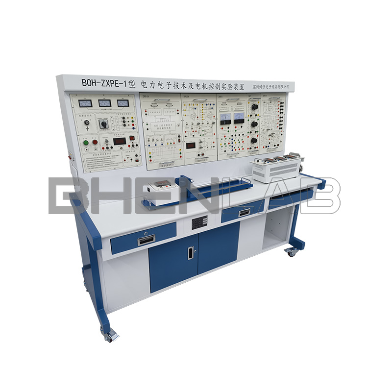
- Size: 1565mm * 720mm * 1650mm
- Weight:<150kg
4、 Completed experimental projects
- Power electronics technology (traditional rectification)
(1) Experimental study on synchronous phase-shifting trigger circuit of single junction transistor
(2) Experimental Study on Sinusoidal Synchronous Phase Shifting Trigger Circuit
(3) Experimental study on sawtooth wave synchronous phase-shifting trigger circuit
(4) TCA785 Trigger Circuit Experiment
(5) Experiment on single-phase half wave rectification circuit
(6) Experiment on Single phase Bridge Half controlled Rectification Circuit
(7) Experiment on single-phase bridge fully controlled rectification and active inverter circuit
(8) Research on Three phase Half wave Active Inverter Circuit with Thyristor
(9) Experiment on Three phase Half wave Controllable Rectification Circuit
(10) Experiment on Three phase Bridge Half controlled Rectification Circuit
(11) Three phase bridge fully controlled rectification and active inverter circuit experiment
(12) Experiment on single-phase AC voltage regulation circuit
(13) Three phase AC voltage regulation circuit experiment
- Power Electronic Device Experiment (Characteristics of Fully Controlled Devices)
(1) Measurement of Main Parameters of Power Field Effect Transistor (MOSFET)
(2) Research on the Drive Circuit of Power Field Effect Transistor (MOSFET)
(3) Research on the Characteristics and Driving Circuit of Insulated Gate Bipolar Transistor (IGBT)
- Power electronics technology (typical circuit part of fully controlled devices)
(1) Performance Study of DC Chopper Circuits (Buck, Cuk, Boost, Sepic, Buck Boost, Zeta, etc.)
5、 Product Technical Function Description
- Safety protection instructions for the experimental bench
The strong current experiment wire adopts a fully plastic enclosed pistol type wire, and the inside of the wire is made of oxygen free copper drawn into strands as thin as hair, with a soft texture. The sheath is made of thick wire diameter and anti hardening chemical products, and the plug is made of solid core copper to avoid the possibility of electric shock caused by students touching the metal parts during live operation.
2) The security protection system of the equipment
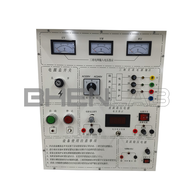
The three-phase AC power output is equipped with dual overcurrent and short-circuit protection functions of electronic circuits and fuses. If the output current is greater than 3A, the power supply can be disconnected and an alarm indication can be given;
The gate cathode of the thyristor and the observation holes of each trigger circuit are equipped with high-voltage protection function to prevent students from misconnecting;
The experimental platform uses three types of experimental wires that cannot be plugged into each other. For strong electricity, a fully plastic enclosed safety experimental wire is used. For weak electricity, a metal exposed experimental wire (with a copper core diameter larger than that of the strong electricity wire) is used. The observation hole uses a 2 # experimental wire to avoid the possibility of students accidentally connecting strong electricity to weak points
The AC/DC power supply of the experimental platform is equipped with overcurrent protection function.
- Technical Description of Control Screen
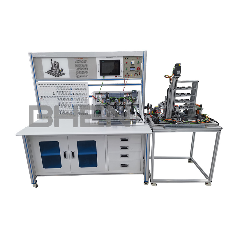
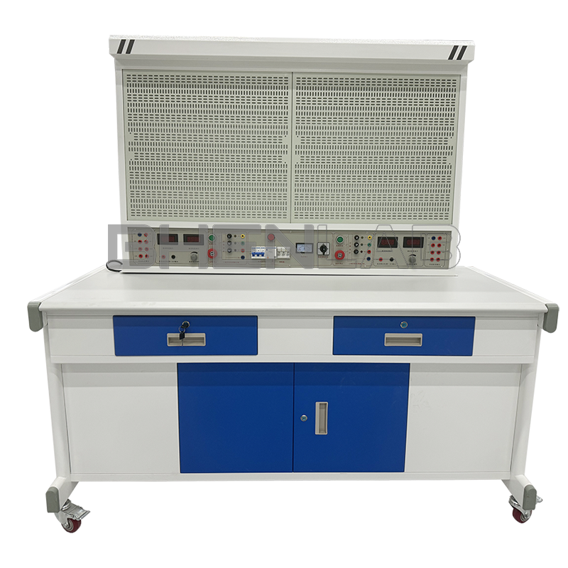
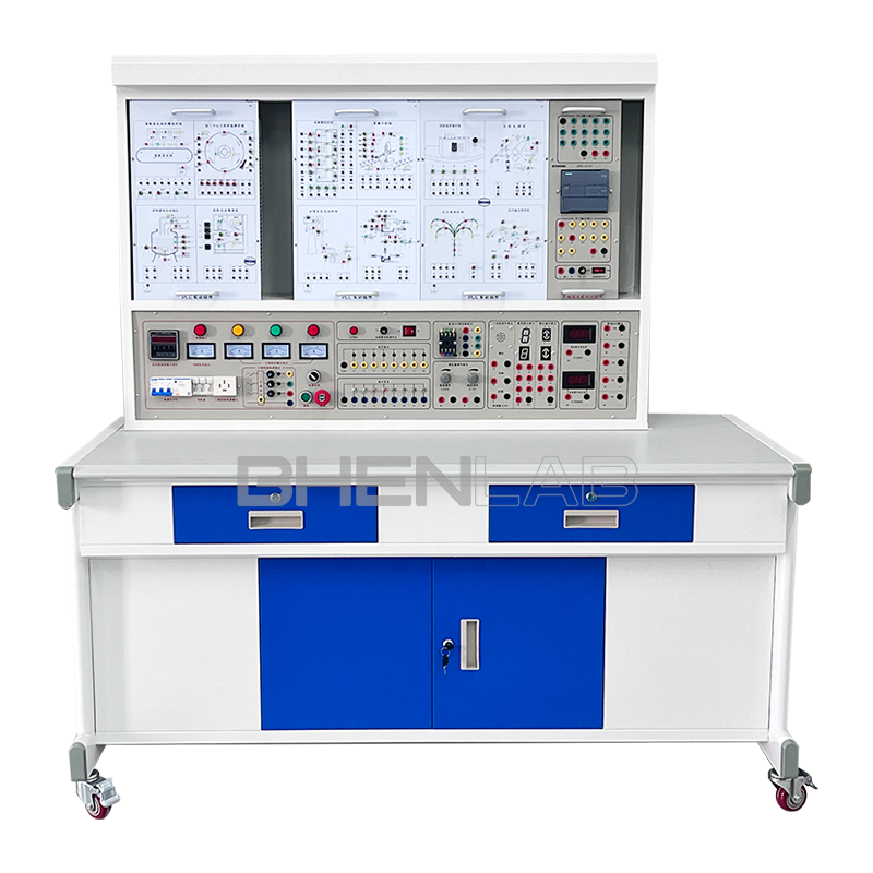
1) BOHPE-02 experimental table
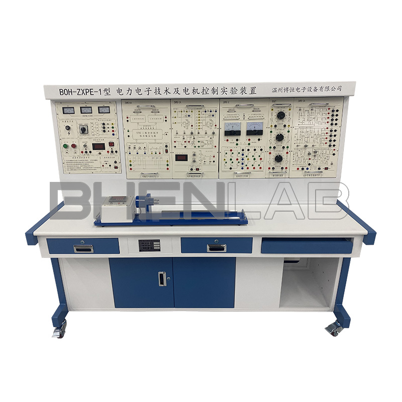
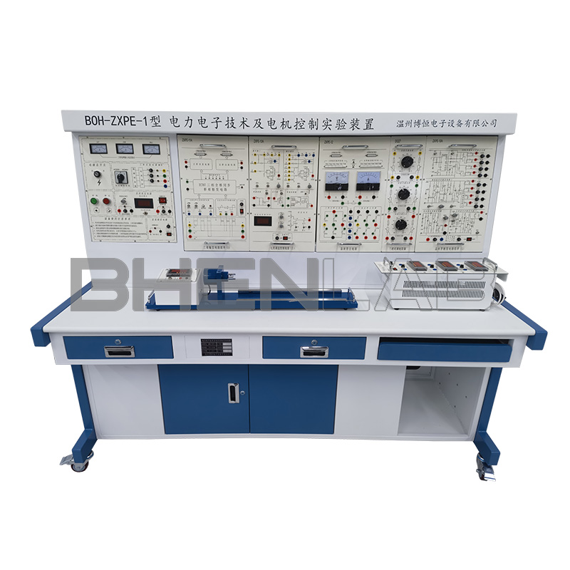
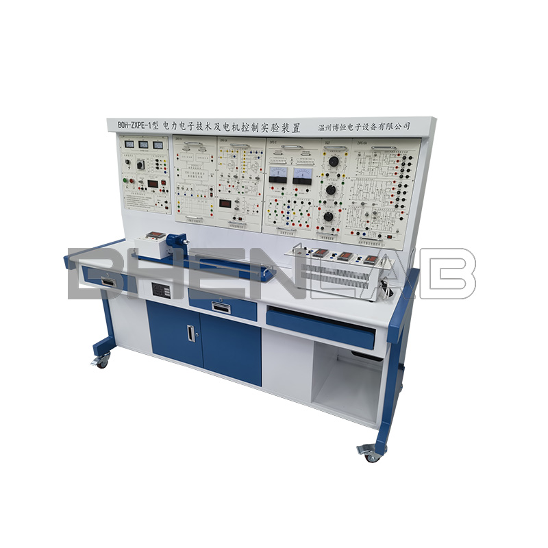
The experimental table is made of aluminum alloy structure, and the tabletop is made of high-density anti-corrosion and fireproof board. The appearance is beautiful and generous, with two drawers and storage cabinets for tools, hanging boxes, and materials. The experiment is equipped with four wheels for easy movement and fixation, which is beneficial for laboratory layout.
2) BOHPE-01 power control module
Provide three-phase AC power supply: output three-phase 220V AC power supply with overcurrent protection. The power supply is used for student experiments after passing through safety protection circuits such as current type leakage protection, three-phase isolation transformer, and voltage type leakage protection.
3) BOHPE-01A Auxiliary Function Module (1)
Provide a given voltage and DC stabilized power supply: provide a 15V/1A DC stabilized power supply; A set of 24V/2A DC stabilized power supply. It has an independent switch and is equipped with short-circuit protection, overcurrent protection, etc.
4) BOHPE-01B Auxiliary Function Module (2)
Three phase transformer: as an inverter transformer in cascade speed control systems and active inverter lines
BOHPE-01C Resistance Load Module
Adjustable resistor: Provide a set of adjustable resistors ranging from 90-1000Q/1A.
6) YB10 AC digital voltmeter
Three AC voltmeters: equipped with communication interface, multi gear automatic range, industrial grade cabinet mounted 48m * 96mm, accuracy: 0.5 level, range: 0-500V, display unit: V, with RS485 communication protocol. Built in TVS protection circuit; The communication address, also known as the communication baud rate, can be modified/queried by lightly touching the panel button. It is very convenient for students to learn communication experiments during experiments. The available address is 1255, and the communication baud rate can be selected from 1200bps, 2400bps, 4800bps, 9600bps, and 19200bps.
7) YB11 AC digital ammeter
Three AC ammeters: equipped with communication interface, multi gear automatic range, industrial grade cabinet mounted 48mm * 96mm, accuracy: 0.5 level, range: 0-5A, display unit: A, with RS485 communication protocol. Built in TVS protection circuit; The communication address, also known as the communication baud rate, can be modified/queried by lightly touching the panel button. It is very convenient for students to learn communication experiments during experiments. The available address is 1255, and the communication baud rate can be selected from 1200bps, 2400bps, 4800bps, 9600bps, and 19200bps.
8) YB12 digital single-phase power and power factor meter
Provide voltage, current, power factor, frequency, apparent power, active power, and reactive power that can measure circuits. The power measurement accuracy is level 0.5, the power factor measurement range is 0.3~1.0, and the voltage and current range is 0-500V/0-5A (measurable from OV/A). Has anti-interference function. Can automatically distinguish the nature of the load (inductive display “L”, capacitive display “C”, pure resistance not displayed). Equipped with RS485 communication protocol. Built in TVS protection circuit; The communication address, also known as the communication baud rate, can be modified/queried by lightly touching the panel button. It is very convenient for students to learn communication experiments during experiments. The available address is 1255, and the communication baud rate can be selected from 1200bps, 2400bps, 4800bps, 9600bps, and 19200bps.
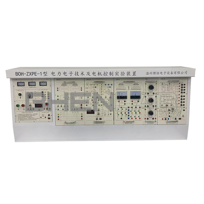
9) BOHPE-10A thyristor trigger circuit component
Provide TCA785 integrated trigger circuit, sawtooth wave synchronous trigger circuit, and sine wave synchronous trigger circuit to lead out various observation holes, so that students can intuitively understand the working principle and process of various trigger circuits. The trigger signal of each trigger circuit has been connected to the corresponding thyristor, making operation convenient and safe.
10) BOHPE-11A Three phase Trigger Circuit Component
Trigger circuit: Using digital integrated circuits, it has strong anti-interference ability, uniform three-phase pulse interval, good consistency, generates double narrow pulses, and the pulse phase shift range is 0-160 °. Six pulse waveforms of three-phase synchronous voltage can be observed on the panel, and the angle a can be controlled through the “Uct” terminal. There are also two pulse control terminals, “Ublr” and “Ublf”, which respectively control the I and II group pulse amplification circuits and are equipped with current feedback and overcurrent protection for current closed-loop experiments.
11) BOHPE-12 three-phase thyristor main circuit component
Main circuit: composed of 12 thyristors and an RC absorption circuit. The thyristor adopts the 6A/800V metal package produced by Shanghai rectifier factory, which has strong overload capacity, high reliability, and strong interference ability. The triggering circuit is controlled through piano key buttons. Reactor: Provides the smoothing reactor and RC filter required for DC speed regulation experiments. The smoothing reactor adopts a center tap method and is rated at 50mH, 100mH, 200mH, and 700mH, respectively. It maintains linearity when the current is less than 1.5A. Reactors can also serve as inductive loads in power electronics technology experiments.
12) BOHPE-12A DC pointer meter component
DC voltmeter: Provide one voltmeter with a measurement range of ± 300V.
DC ammeter: Provide one ammeter with a measurement range of ± 2A.
13) BOHPE-10C thyristor trigger circuit component (III)
The three-phase bridge rectifier circuit composed of 6 diodes and the single junction transistor trigger circuit lead out various observation holes, allowing students to intuitively understand the working principle and process of various trigger circuits. The trigger signal of each trigger circuit has been connected to the corresponding thyristor, making the operation convenient and safe.
14) BOHPE-14 power device
In addition to studying the driving circuit and switching characteristics of MOSFET and IGBT devices, this experimental box can also analyze the application of fast recovery diodes, high-speed optocouplers, inductors, etc. in power electronic circuits. When designing the panel, there are many waveform observation holes left. By changing the circuit parameters, it is convenient for students to analyze the situation of each working point and understand the changes in device characteristics caused by parameter changes. When designing the circuit, the principle of “easy first, difficult later” and “separation first, integration later” was followed. Several common and practical driving circuits were selected to enable students to apply what they have learned.
15) BOHPE-15 DC chopper circuit
Provide the components required to form a DC chopper circuit and use a dedicated PWM control integrated circuit SG3525. Six typical experiments can be completed, including Buck Chopper, Boost Chopper, Boost Buck Chopper, Cuk Chopper, Sepic Chopper, and Zeta Chopper. All circuits use discrete components, and students conduct experiments by building them themselves.
- BOHPJ-01 experimental wire
The experimental connection wire adopts a highly reliable fully enclosed pistol plug type, with 128 strands of oxygen free copper drawn into a hair like thin wire inside, soft texture, and a protective sheath made of thick wire diameter and anti hardening chemical products. The plug is made of solid core copper.